Gas stop structure capable of repeated inflation and deflation

a technology of gas stop and gas stop, which is applied in the direction of flexible container closure, functional valve type, containers, etc., can solve the problems of gas leakage from the packing bag, inconvenience for users of such a gas packing bag, and difficulty in inserting the gas tube into the packing bag, so as to prolong the service life and reduce user costs. , the effect of convenient gas tube inser

Active Publication Date: 2013-11-26
AIR BAG PACKING +1
View PDF34 Cites 11 Cited by
  • Summary
  • Abstract
  • Description
  • Claims
  • Application Information

AI Technical Summary

Benefits of technology

[0007]Accordingly, the present invention provides a gas stop structure capable of repeated inflation and deflation, which includes: a plurality of outer films; a gas chamber area, formed through heat-seal bonding of the plurality of outer films and including a buffer portion and a gas storage portion, in which an area of the buffer portion is smaller than an area of the gas storage portion; a gas stop valve, located between the plurality of outer films through heat-seal bonding, in which a part of the gas stop valve is located in the buffer portion, and another part is exposed beyond the plurality of outer films; and a warp portion, formed through heat-seal bonding of the plurality of outer films and located between the buffer portion and the gas storage portion, in which the warp portion includes a connecting hole through which the buffer portion and the gas storage portion are in communication. When a gas tube is placed inside the gas stop valve to inflate the gas chamber area with gas, a height of the inflated gas storage portion is greater than that of the buffer portion, forming a sectional difference, so the gas storage portion bends towards the buffer portion with the warp portion as a central point to seal the connecting hole. As a result, the gas in the buffer portion presses the gas stop valve to close the gas stop valve, achieving a double gas closure effect.
[0008]The present invention also provides a gas stop structure capable of repeated inflation and deflation, which includes: a plurality of outer films; a gas stop valve located between the plurality of outer films through heat-seal -bonding, in which the gas stop valve includes a plurality of first inner films, a plurality of second inner films and a buffer portion, a part of the plurality of first inner films is exposed beyond the plurality of outer films, a plurality of second inner films is located between the plurality of first inner films and is partially exposed beyond the plurality of first inner films, the buffer portion is located between the plurality of first inner films, and an area of the buffer portion is smaller than an area of a gas storage portion; and a warp portion, formed through heat-seal bonding of the plurality of outer films and located between the buffer portion and the gas storage portion, in which the warp portion includes a connecting hole through which the buffer portion and the gas storage portion are in communication. When the gas storage portion is inflated with gas through the gas stop valve, the gas inside the gas storage portion presses the gas stop valve to seal the connecting hole. The gas in the buffer portion consequently presses the plurality of second inner films, so that each film in the plurality of second inner films adheres to the other to achieve a double gas closure effect.
[0009]In the present invention, a small buffer portion and a large gas storage portion are formed in the gas chamber area by means of heat-seal bonding. During inflation, the gas first flows into the buffer portion through the gas stop valve and then flows into the gas storage area through the connecting hole to for inflation and expansion. As an area of the buffer portion is small, an internal pressure thereof after inflation is low. In addition, a gas inlet position where the gas stop valve is located is inside the buffer portion, so that a resistance for the gas tube to be inserted into the buffer portion through the gas passage of the gas stop valve is small. It is therefore convenient to insert the gas tube. In this manner, the gas storage portion is capable of repeated inflation and deflation, prolonging its service life and reducing user costs.

Problems solved by technology

However, in practical applications, as the two films of the gas stop valve are adhered under the gas pressure inside the packing bag, it is very difficult to insert the gas tube into the packing bag through the gas passage of the gas stop valve for discharge.
In some cases, the gas tube might even damage the gas stop valve (for example, the gas tube pierces through the gas stop valve to damage the films thereof), and cause gas leakage from the packing bag.
As a result, deflation becomes impossible and the packing bag cannot be inflated and used again, causing inconvenience to users of such a gas packing bag.

Method used


Image

  • Gas stop structure capable of repeated inflation and deflation
  • Gas stop structure capable of repeated inflation and deflation
  • Gas stop structure capable of repeated inflation and deflation

Examples


first embodiment

[0025]FIG. 1, FIG. 2, FIG. 3 and FIG. 4A show a gas stop structure capable of repeated inflation and deflation according to the present invention.

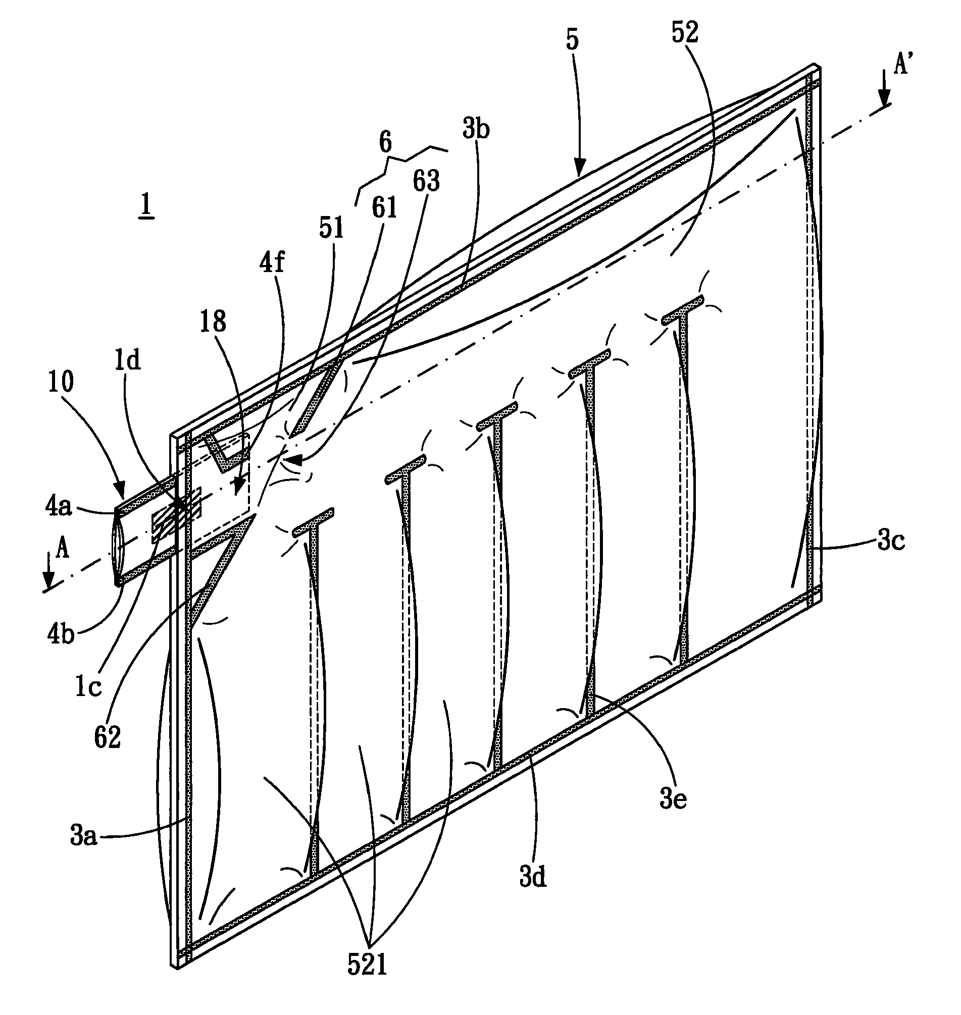
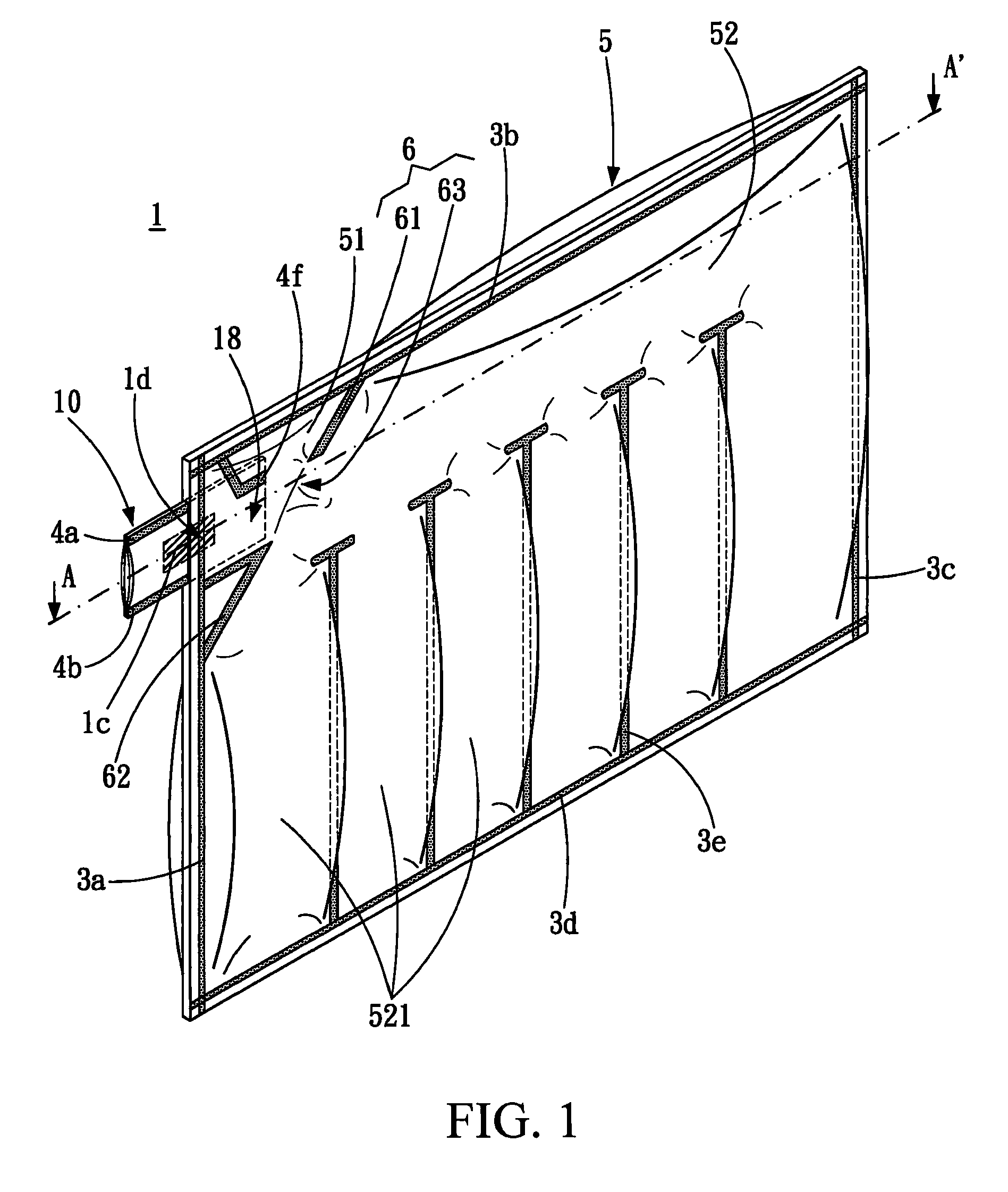
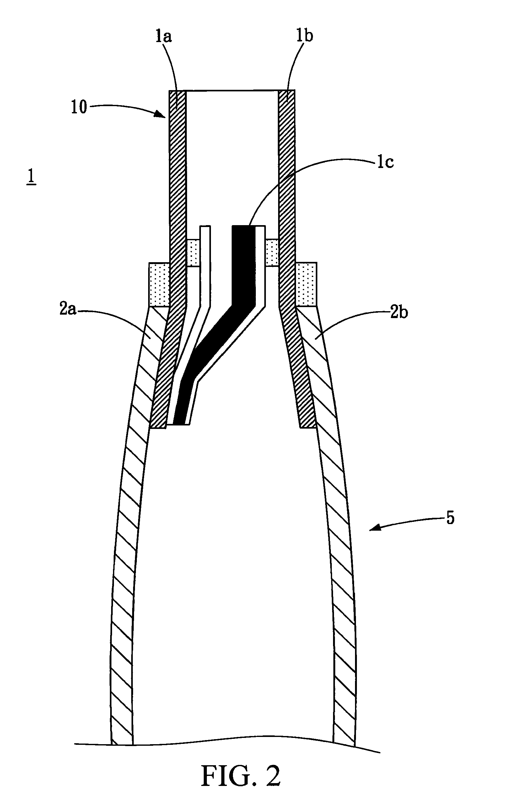
[0026]A gas stop structure capable of repeated inflation and deflation 1 of the present invention includes two outer films 2a and 2b, two first inner films 11a, a gas stop valve 10, a gas chamber area 5 and a warp portion 6.

[0027]The two outer films 2a and 2b are stacked vertically, and may form bonding of heat seal lines 3a, 3b, 3c and 3d by means of heat sealing to form the gas chamber area 5. After the gas chamber area 5 is formed between the two outer films 2a and 2b by means of heat sealing, the warp portion 6 may be formed by means of heat sealing. A space between the two outer films 2a and 2b is divided into a buffer portion 51 and a gas storage portion 52, in which an area of the buffer portion 51 is smaller than an area of the gas storage portion 52. Furthermore, the gas storage portion 52 may be divided into a plurality of smalle...


PUM


Abstract

A gas stop structure capable of repeated inflation and deflation is provided, which includes: a plurality of outer films; a gas chamber area, formed of the plurality of outer films and including a buffer portion and a gas storage portion; a gas stop valve, located between the plurality of outer films, in which a part of the gas stop valve is exposed beyond the plurality of outer films; and a warp portion, connected the buffer portion and the gas storage portion. When a gas tube is placed inside the gas stop valve to inflate the gas chamber area with gas, a height of the inflated gas storage portion is greater than that of the buffer portion to form a sectional difference, so the gas storage portion bends towards the buffer portion to seal the warp portion. After inflation, the gas tube is removed and the gas stop valve is sealed.

Description

CROSS-REFERENCES TO RELATED APPLICATIONS[0001]This non-provisional application claims priority under 35 U.S.C. §119(a) on Patent Application No. 100120003 filed in Taiwan, R.O.C. on 2011 Jun. 08, the entire contents of which are hereby incorporated by reference.BACKGROUND OF THE INVENTION[0002]1. Technical Field[0003]The present invention relates to a gas packing bag structure, and more particularly to a gas stop structure capable of repeated inflation and deflation.[0004]2. Related Art[0005]A gas stop valve is disposed in a gas packing bag formed of enclosed plastic films through heat-seal bonding. The gas packing bag may be inflated with gas from outside through the gas stop valve. Furthermore, the gas stop valve stops air backflow to prevent the gas inside the packing bag from leaking. The gas stop valve is generally formed of two films partially adhered to each other with a gas passage being formed between the two films by means of heat-seal bonding, so that the packing bag may ...

Claims


Application Information

Patent Timeline
Patent Type & Authority Patents(United States)
IPC IPC(8): F16K15/14
CPCB65D81/052Y10T137/3584Y10T137/7882B65D31/12B65D31/14B65D81/03B65D81/07
Inventor JIAN, BO-XINLIAO, CHIEH-HUALIAO, YAW-SHIN
Owner AIR BAG PACKING
Why Eureka
Try Eureka