Reception device and reception method

a reception device and a technology for detecting signals, applied in the field of detecting signals and receiving methods, can solve the problems of degrading the reception accuracy of the desired signal in the reception device, and achieve the effect of suppressing the increase in circuit size and processing time, and reducing the effect of interference signals

Inactive Publication Date: 2013-11-26
NIPPON TELEGRAPH & TELEPHONE CORP
View PDF21 Cites 4 Cited by
  • Summary
  • Abstract
  • Description
  • Claims
  • Application Information

AI Technical Summary

Benefits of technology

[0019]In the reception device constituted as described above, the interference signal frequency position detection section detects the frequency position of the interference signal when the interference signal is included in a signal received by the reception section, and the filter section suppresses the multicarrier signal and the interference signal at the frequency position from which the interference signal is detected. A circuit for constituting the interference signal frequency position detection section and the filter section has a small circuit size compared to a circuit for constituting a generation section generating an interference replica in the related art. A processing time necessary for the interference signal frequency position detection section and the filter section is short compared to processing for generating the interference replica in the related art.
[0020]Accordingly, the present invention can reduce the effect of an interference signal while suppressing increases in circuit size and processing time.

Problems solved by technology

This causes a problem in that the reception accuracy of the desired signal is degraded in the reception device by the interference signal received by the reception device along with the desired signal.

Method used


Image

  • Reception device and reception method
  • Reception device and reception method
  • Reception device and reception method

Examples


modified example

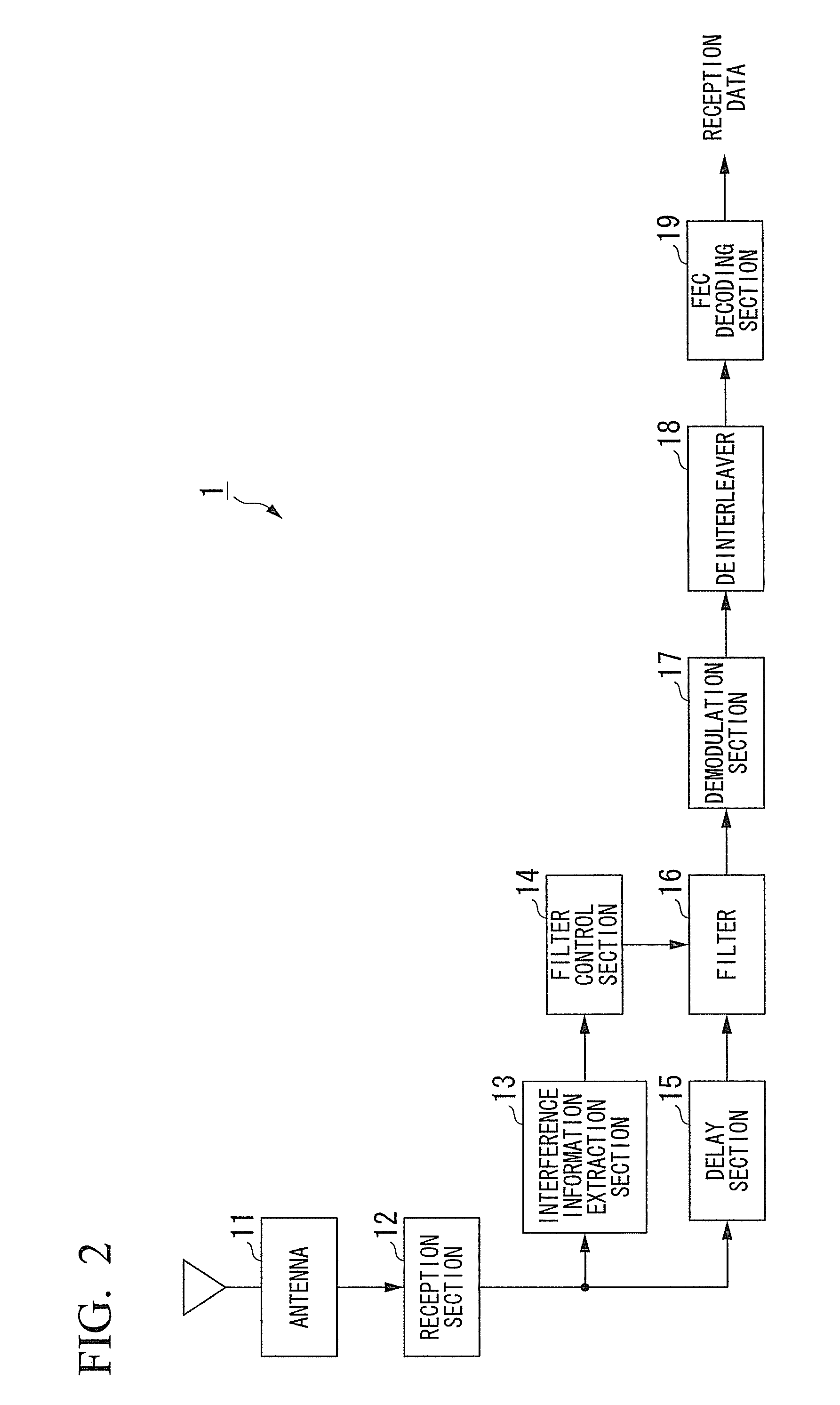
[0076]A configuration in which the delay section 15 provided in the reception device 1 delays a reception signal and thus the filter 16 filters the reception signal referred to by the filter control section 14 upon decision of parameters based on a filter of the parameters set by the filter control section 14 has been described in the above-described embodiment, but the reception device 1 may not be provided with the delay section 15. In this case, when filtering is performed, the parameters set by the filter 16 are parameters decided based on interference information extracted from a reception signal received before the reception signal serving as a filtering target. Accordingly, a difference may occur between a cutoff frequency of a filter set to the filter 16 and the interference information extracted from the reception signal serving as the filtering target. However, a reception timing difference between the filtered reception signal and the reception signal referred to upon par...


PUM


Abstract

It is possible to reduce the effect of an interference signal while suppressing increases in a circuit scale and a processing time. A reception device receives a multicarrier signal and an interference signal via a radio transmission path, detects a frequency position of the interference signal, performs filtering to suppress the multicarrier signal and the interference signal at the detected frequency position of the interference signal, removes a guard interval from the multicarrier signal suppressed by the filtering, demodulates each subcarrier of the multicarrier signal from which the guard interval is removed, and performs error correction on the demodulated signal.

Description

TECHNICAL FIELD[0001]The present invention relates to a reception device and a reception method which reduce the effect of an interference signal in a multicarrier transmission scheme.[0002]Priority is claimed on Japanese Patent Application No. 2008-192465 filed on Jul. 25, 2008, the content of which is incorporated herein by reference.BACKGROUND ART[0003]Recently, with the spread of wireless communication devices, signals of various frequency bands have been propagated in the air. Thus, when a desired signal (hereinafter, referred to as a “desired signal”) is received, a reception device receives an interference signal in the same frequency band as that of the desired signal, along with the desired signal. This causes a problem in that the reception accuracy of the desired signal is degraded in the reception device by the interference signal received by the reception device along with the desired signal.[0004]To solve this problem, a technique has been proposed which generates a re...

Claims


Application Information

Patent Timeline
Patent Type & Authority Patents(United States)
IPC IPC(8): H03D1/04
CPCH04B1/1027H04J11/0066H04L27/2647H04L1/0056H04L1/0052H04L27/2691
Inventor MASHINO, JUNSUGIYAMA, TAKATOSHI
Owner NIPPON TELEGRAPH & TELEPHONE CORP
Why Eureka
Try Eureka