Single operator multitask robotic platform

a robotic platform and single operator technology, applied in the field of robotics, can solve the problems of prone to being targeted by the enemy, units cannot protect mechanized units traveling at high speeds, and units cannot return precise information about a scen

Inactive Publication Date: 2013-11-26
DEFENSE VISION
View PDF7 Cites 22 Cited by
  • Summary
  • Abstract
  • Description
  • Claims
  • Application Information

AI Technical Summary

Benefits of technology

[0042]An embodiment of a method for a single human operator to control a robotic platform may further include supplying information on events occurring around a vehicle or engaging threats to a vehicle while the robotic platform is being transported by the vehicle. The supplying of information and engaging of threats may be performed using the synchronized factors in the disengaged mode.
[0043]An embodiment of a method for a single human operator to control a robotic platform may further include utilizing an intuitive power of the human operator. The intuitive power may include binocular depth perception, peripheral motion detection, tracking or stereo audio perception.
[0044]An embodiment of a method for a single human operator to control a robotic platform may further include changing a modular assembly including the synchronized factors.
[0045]An embodime

Problems solved by technology

Amongst other limitations, K9 units can only recognize certain kinds of threats, K9 units can only engage relatively soft threats, K9 units cannot protect mechanized units traveling at high speeds and K9 units cannot return precise information about a scene ahead of the force.
However, because such platforms play a vital part in operations, they are also prone to be targeted by the enemy.
Another major challenge which is well known in the art of robotics is the ability to effectively drive a robotic platform, especially under chaotic operational conditions.
Even when physical means are provided for operating and driving in differen

Method used


Image

  • Single operator multitask robotic platform
  • Single operator multitask robotic platform
  • Single operator multitask robotic platform

Examples


Embodiment Construction

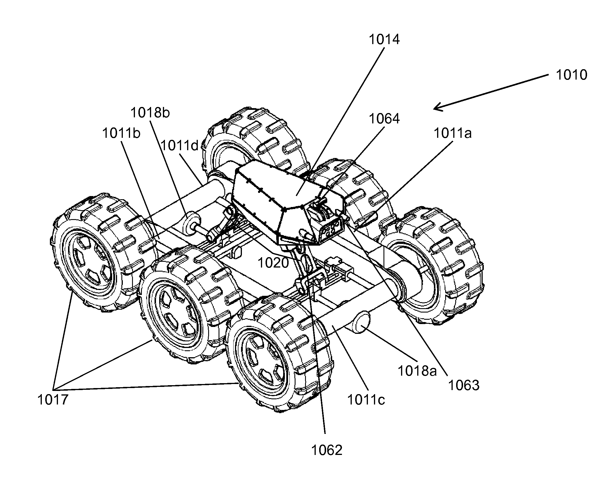
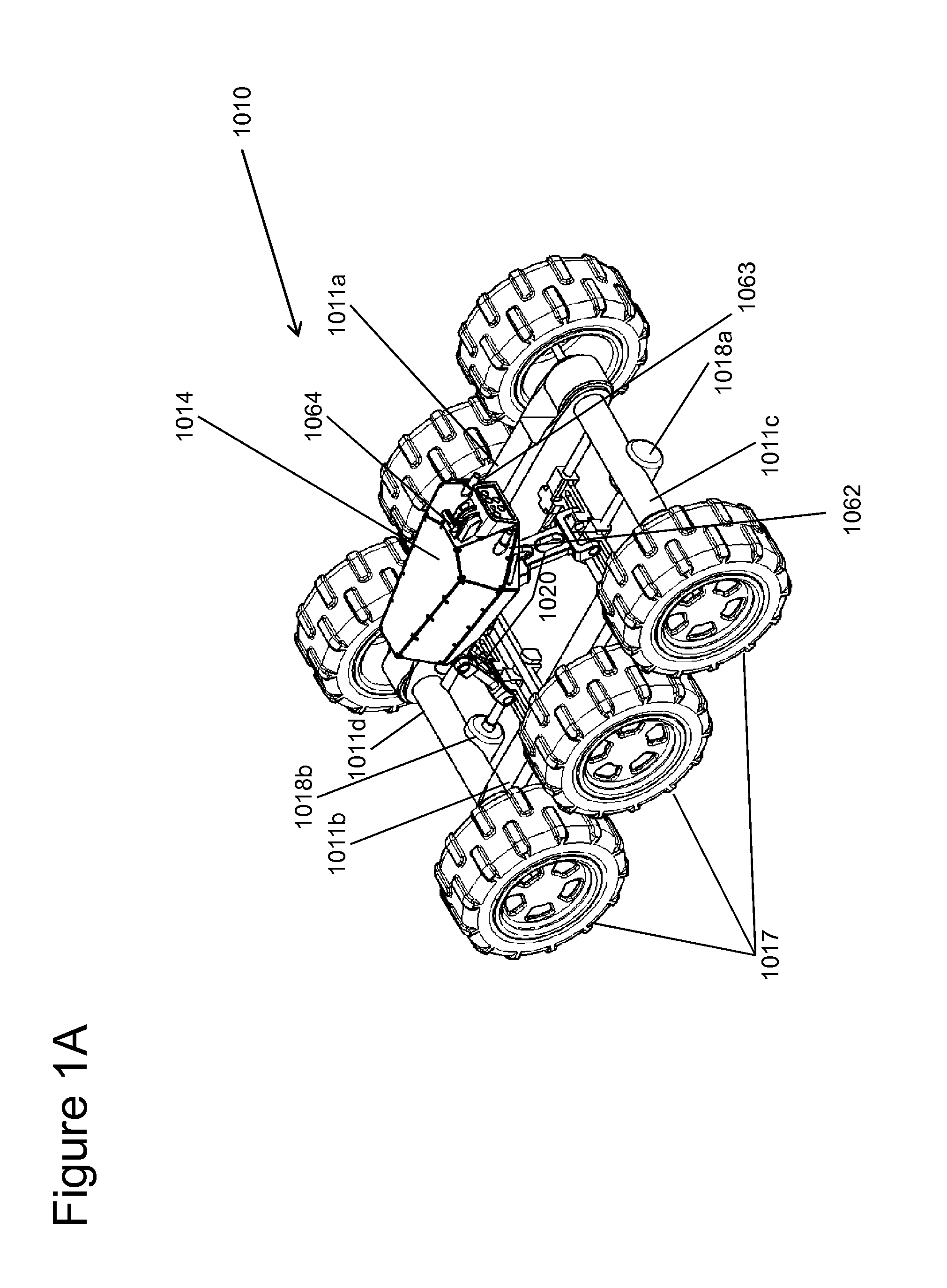
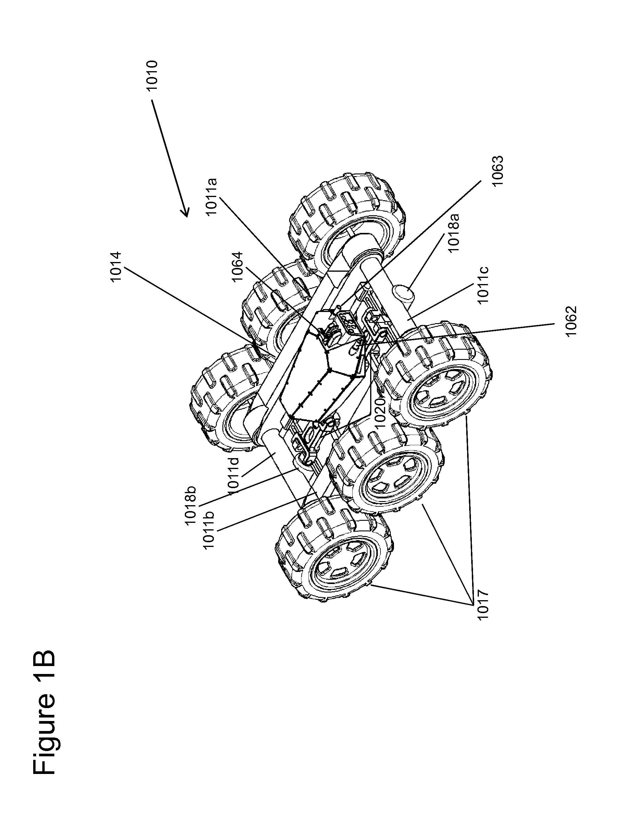
[0059]For a better understanding of the invention and to show how the same may be carried into effect, reference will now be made, purely by way of example, to the accompanying drawings. With specific reference to the drawings in detail, it is stressed that the particulars shown are by way of example and for purposes of illustrative discussion of preferred embodiments of the present invention only, and are presented for the purpose of providing what is believed to be the most useful and readily understood description of the principles and conceptual aspects of the invention. In this regard, no attempt is made to show structural details of the invention in more detail than is necessary for a fundamental understanding of the invention. From the description taken together with the drawings it will be apparent to those skilled in the art how the several forms of the invention may be embodied in practice. Moreover, it is to be understood that the phraseology and terminology employed here...


PUM


Abstract

A robotic platform is capable of multi-tasking under control of a single remote operator. The platform may include a turret mounted on a positioning mechanism. The turret may incorporate an imaging sensor, a target designator and a weapon in a synchronized manner. The robotic platform is capable of switching between different modes: (i) an engaged mode, in which the turret is aligned with the preferred direction of travel of the platform; in the engaged mode the turret is designated by maneuvering the entire robotic platform; (ii) a disengaged mode, in which the robotic platform faces in a first direction while the turret faces another direction to acquired targets. Various functions of driving the platform and operating the turret may be automated to facilitate control by a single operator.

Description

[0001]This patent application claims the benefit of U.S. Provisional Patent Application No. 61 / 302,558 filed 9 Feb. 2010.FIELD AND BACKGROUND OF THE INVENTION[0002]The present invention is related to the field of robotics; more specifically the invention is related to the field of electro-mechanics for providing a robotic platform including enhanced operational capabilities for performing multiple tasks simultaneously under the control of a single human operator.[0003]The art of robotics has increasingly developed throughout the years, many solutions have been offered by the art in order to overcome the various challenges inherent in the robotics field.[0004]The solutions offered by the art are usually customized to the requirements for which a robotic platform is designed.[0005]Robotic platforms are utilized for various operations such as reconnaissance and dismantling bombs. Armed robots even participate in actual warfare at the operational scene. Robots also participate in search...

Claims


Application Information

Patent Timeline
IPC IPC(8): G05B19/04G06F19/00
CPCF41H7/005
Inventor GAL, EHUD
Owner DEFENSE VISION
Why Eureka
Try Eureka