Simultaneously displaying multiple call stacks in an interactive debugger

a debugger and call stack technology, applied in the direction of visual/graphical programming, program control, instruments, etc., can solve the problem that microsoft debuggers have not provided tools for consolidating and viewing information from multiple call stacks

Active Publication Date: 2013-11-26
MICROSOFT TECH LICENSING LLC
View PDF8 Cites 16 Cited by
  • Summary
  • Abstract
  • Description
  • Claims
  • Application Information

AI Technical Summary

Benefits of technology

[0006]In some embodiments, users can command a debugger to display a stack segments graph based on call stacks from all tasks, based on call stacks from all threads, or based on call stacks of tasks or threads which have been flagged by a user. In some, the debugger displays details of a stack frame, details of a thread, and / or details of a task. In some embodiments, a debugger's graphical user interface displays an indication visually distinguishing (from the surrounding information) an active stack frame of a current thread, an active stack frame of a current task, an active stack frame of a non-current thread, and / or an active stack frame of a non-current task. In some embodiments, a debugger's graphical user interface displays an indication distinguishing a current thread, and / or an indication visually distinguishing a current task. In some embodiments, a user can select a non-current frame to become a newly current frame, and a debugger window is then updated based on the newly current frame. Some embodiments allow a user to zoom in on a particular area of the visual representation of the stack segments graph, to zoom out to a view displaying the entire graph, and / or to drag-pan across the graph.

Problems solved by technology

Even so, Microsoft debuggers have not provided tools for consolidating and viewing information from multiple call stacks; users have been required to switch focus from stack to stack in order to get information about multi-threaded program state.

Method used


Image

  • Simultaneously displaying multiple call stacks in an interactive debugger
  • Simultaneously displaying multiple call stacks in an interactive debugger
  • Simultaneously displaying multiple call stacks in an interactive debugger

Examples


Embodiment Construction

[0016]Overview

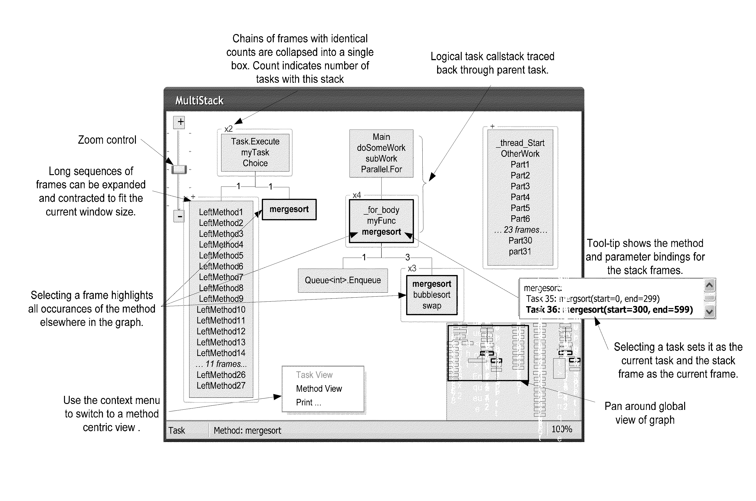
[0017]A debugger user often needs to understand the current execution state of a program being debugged. In particular, understanding the content of the program's call stacks may be necessary to identify a bug. The user navigates through the program, examining details of the program state based on the user's understanding of the call stacks and other aspects of the program. Gaining adequate understanding of call stacks in programs which have multiple threads of execution can be difficult when the user is required to piece together a mental picture from a series of linear stack trace lists. Navigating the program state based on this mental model can be arduous and error prone when it involves a long series of steps.

[0018]Some embodiments described herein provide a convenient tool to view and navigate the program state via a graphical display of the content of multiple program stacks. Multiple stacks are consolidated in a manner that factors out common elements to reduce...


PUM


Abstract

Visual representations of multiple call stacks in a parallel programming system include a stack segments graph constructed by coalescing data from multiple stacks. The graph has nodes that represent stack segments and has arcs between adjacent segments. Similar stack frames are represented by the same node. In a stack prefix view of the graph, arcs are directed from a node representing stack frames to a node representing subsequently executed stack frames. In a method-centered view, an arc is shown between a node representing stack frames of a selected method and a node representing adjacent stack frames. The graph can be based on call stacks of all tasks or all threads, or based on call stacks of tasks or threads flagged by a user. Stack frame, thread, and / or task details are also displayed.

Description

BACKGROUND[0001]Sometimes a computational problem can be divided into pieces in a way that allows a system to work on more than one piece at a time. For example, concurrent computer programs simultaneously carry out multiple computing tasks, using mechanisms such as multiple threads or multiple computational processes. Parallel computing may be viewed as an example of concurrent computing, and the distinction between them is not critical here.[0002]Parallel programs, like many other programs, are generally developed using tools such as source code editors, version control systems, documentation generators, compilers, interpreters, virtual machines, performance profilers, and / or debuggers. A debugger, in particular, is a computer program used to test and debug other programs, which are referred to as debuggee programs or simply as “debuggees”. A debugger generally provides a software developer with some control over debuggee execution, such as pausing execution to examine the debugge...

Claims


Application Information

Patent Timeline
Patent Type & Authority Patents(United States)
IPC IPC(8): G06F9/44
CPCG06F11/3636G06F11/3664G06F8/34
Inventor MAYBEE, PAULMOTH, DANIELMARIEN, JOHAN
Owner MICROSOFT TECH LICENSING LLC
Why Eureka
Try Eureka