Automatic transmission

a transmission and automatic technology, applied in the direction of gearing details, brake systems, transportation and packaging, etc., can solve the problems of difficult to increase the strength of the transmission case, the internal structure of the transmission casing and/or the transmission casing is considered/designated differently, etc., and achieves the effect of more efficien

Active Publication Date: 2013-12-03
JATCO LTD +1
View PDF16 Cites 38 Cited by
  • Summary
  • Abstract
  • Description
  • Claims
  • Application Information

AI Technical Summary

Benefits of technology

[0005]It is, therefore, in view of the previously-described disadvantages of the prior art, an object of the invention to provide an automatic transmission configured to ensure decentralization of a load (a reaction force) applied from a transmission output shaft through a parking-lock mechanism to a transmission casing without high localized load application to the transmission casing in a parking range, and also configured to enable more efficient assembly work of the parking-lock-mechanism equipped automatic transmission.

Problems solved by technology

This leads to the problem of a considerable layout / design change in the internal structure of the transmission casing and / or the transmission-case shape.
Hence, it is not easy to increase the strength of the transmission case as a countermeasure against the concentrated load.
Additionally, the parking-lock-mechanism equipped automatic transmission disclosed in JP2007-205383 also suffers from the disadvantages of a troublesome positioning of the parking-lock mechanism when installing on the transmission case, and undesirable deviations of the internal linkages constructing the parking-lock mechanism (e.g., the parking rod and the like), from their desired installation positions, in other words, the problem of the deteriorated assembly work when the transmission case and the converter housing are integrally connected to each other.

Method used


Image

  • Automatic transmission
  • Automatic transmission
  • Automatic transmission

Examples


Embodiment Construction

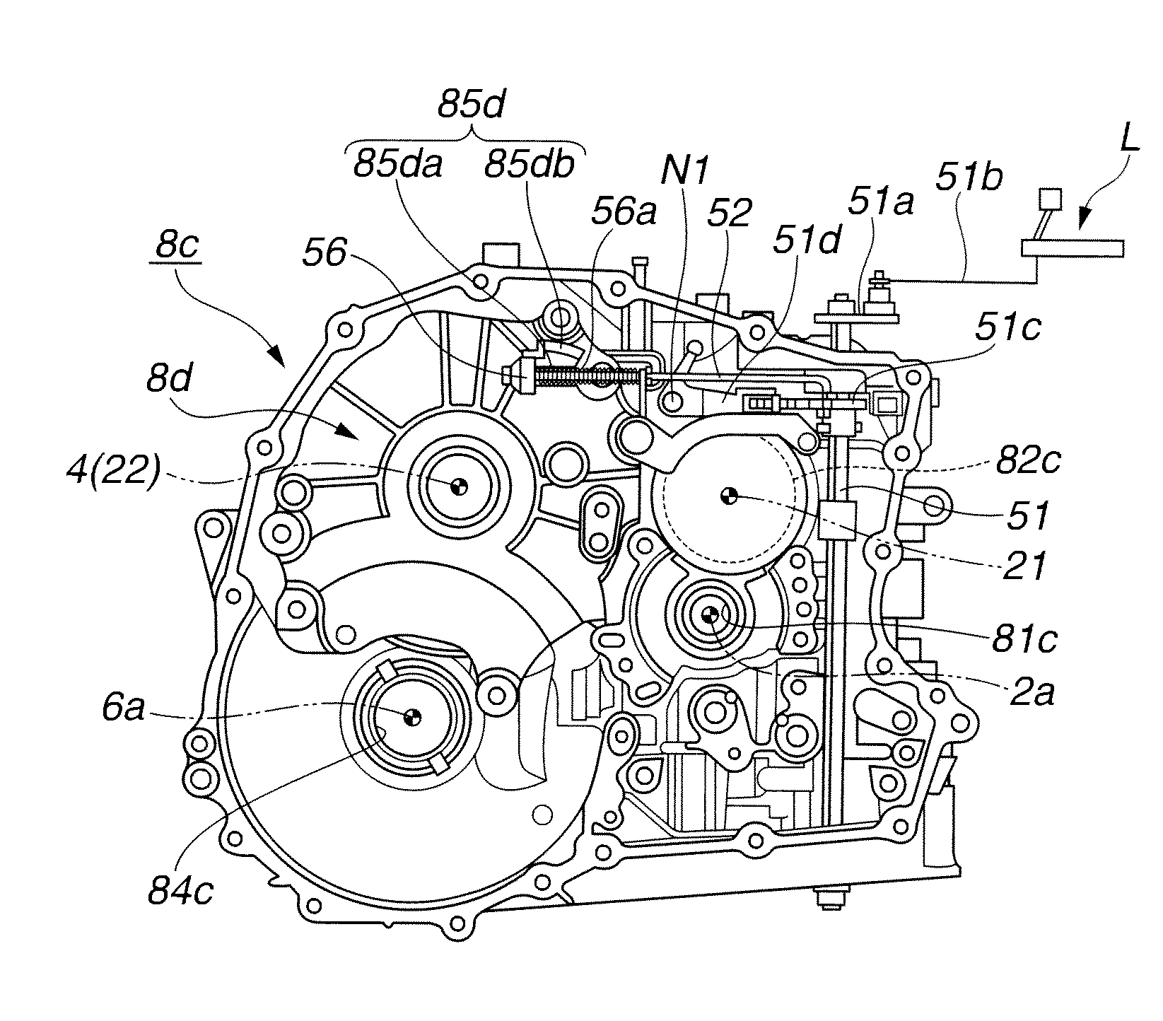
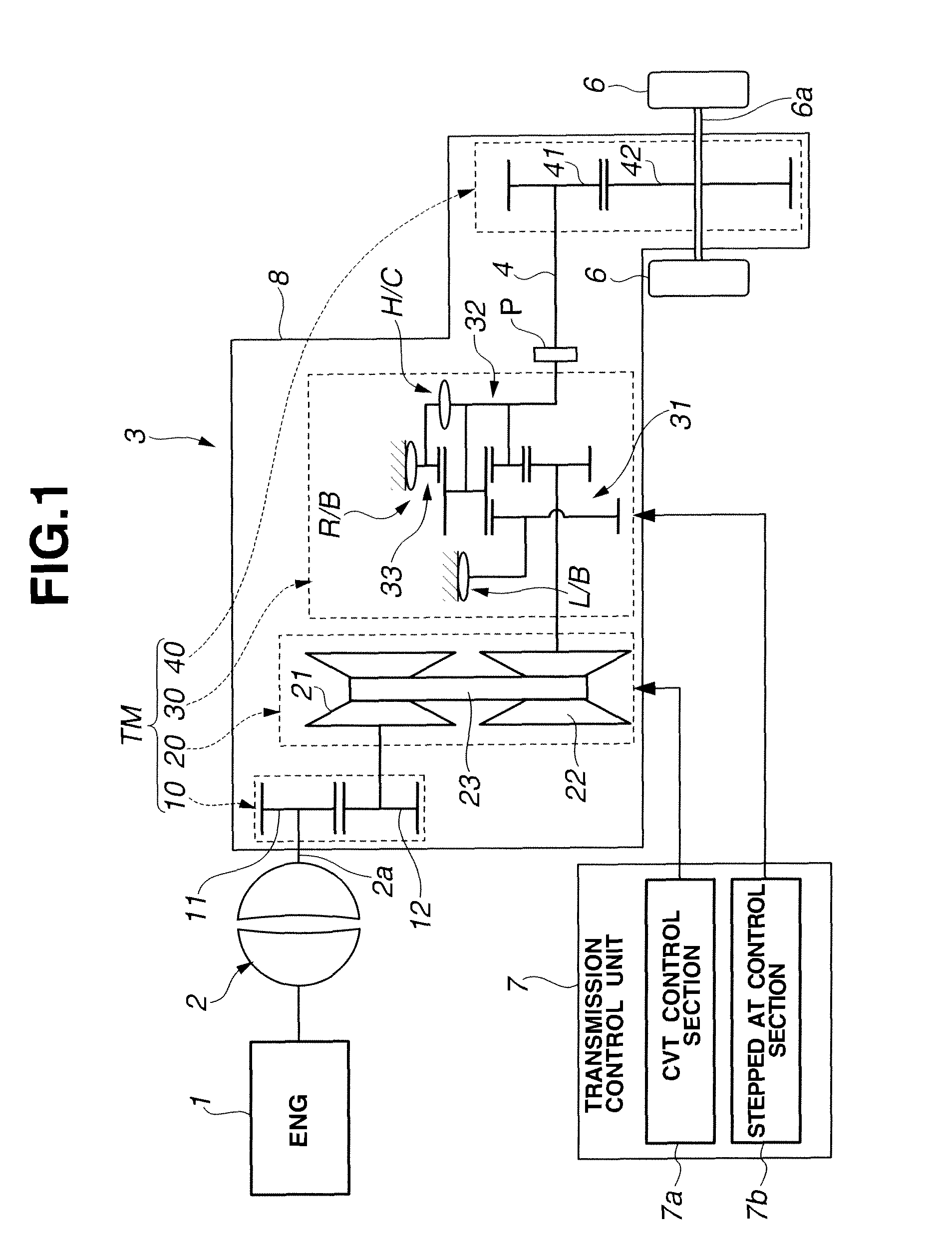
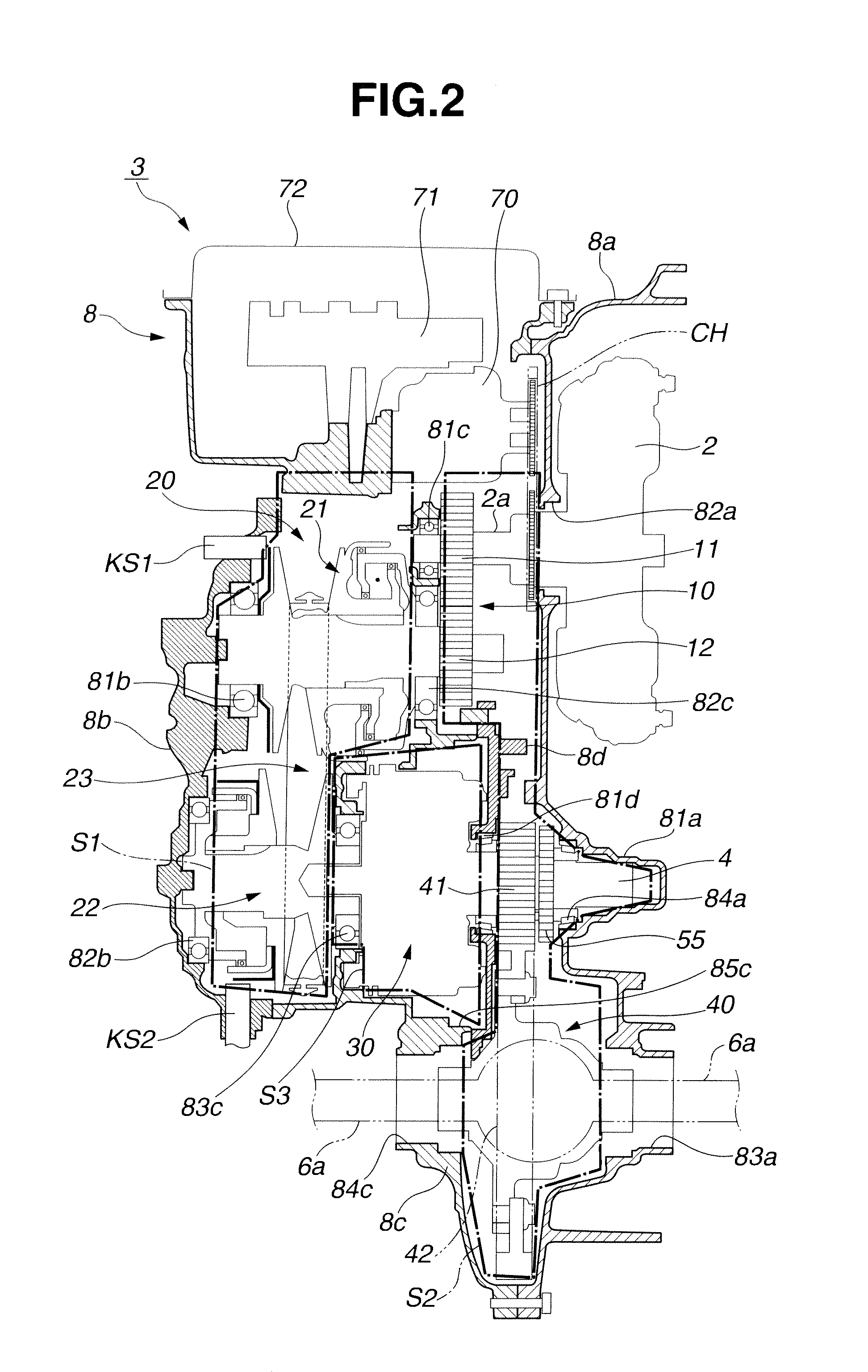
[0014]Referring now to the drawings, particularly to FIGS. 1-2, the automatic transmission of the embodiment is exemplified in a power train of an automotive vehicle.

[0015]As shown in FIG. 1, the power train carries power output from an engine 1 (a source of driving power) to road wheels 6, 6. The power train is comprised of a torque converter 2, an automatic transmission 3, and axle driveshafts 6a, 6a. Automatic transmission 3 has a driven connection with an output shaft 2a of torque converter 2. The power is delivered from automatic transmission 3 via axle driveshafts 6a, 6a to respective road wheels 6, 6. The shifting operation of automatic transmission 3 is controlled by means of a transmission control unit 7. Transmission control unit 7 is comprised of a continuously variable automatic transmission (CVT) control section 7a and a stepped automatic transmission (AT) control section 7b. CVT control section 7a is provided to control the operation of a continuously variable automati...


PUM


Abstract

In an automatic transmission employing a parking-lock mechanism accommodated in a transmission casing for mechanically locking and unlocking a transmission output shaft of a speed-change system, the transmission casing includes a first casing and a second casing integrally connected to each other. A shift-lever-operated manual shaft and a cam-equipped parking rod are installed on the first casing, whereas a support actuator having a guide face for the cam and a pivotable parking pawl operated by the cam for meshed-engagement with a parking gear of the transmission output shaft when a specified longitudinal displacement of the parking rod has been reached are installed on the second casing. A temporary-retaining structure is provided on a transmission-output-shaft bearing retaining wall fixedly connected to a face of the first casing facing the second casing, for temporarily retaining the cam attached to the tip of the parking rod.

Description

TECHNICAL FIELD[0001]The present invention relates to an automatic transmission having a parking-lock mechanism.BACKGROUND ART[0002]As is generally known, an automotive automatic transmission, which is configured to automatically accomplish upshifting and downshifting, employs a parking-lock mechanism installed in a transmission casing. The parking-lock mechanism is comprised of several internal linkages installed in the transmission casing, namely, a manual shaft, a parking-pawl-actuator rod (simply, a parking rod), a support actuator, and a parking pawl. The manual shaft is configured to rotate in synchronism with movement of a shift lever whose position is selectable by the driver. The parking rod is configured to displace in its longitudinal direction in synchronism with rotary motion of the manual shaft. The support actuator has a sloped face onto which a cam, attached to the tip of the parking rod, runs when a specified longitudinal displacement of the parking rod has been rea...

Claims


Application Information

Patent Timeline
Patent Type & Authority Patents(United States)
IPC IPC(8): B60T1/06F16H63/34F16H57/02F16H57/023F16H57/03
CPCF16H63/3416Y10T477/644Y10T74/2186B60T1/06F16H57/02F16H57/023F16H57/03
Inventor WATANABE, HIDEHIKOHIGAKUBO, NOBORUSAKAGUCHI, MASATAKA
Owner JATCO LTD
Why Eureka
Try Eureka