Liquid ejecting head, liquid ejecting apparatus, and method of manufacturing liquid ejecting head

a liquid ejector and liquid ejector technology, applied in metal-working devices, printing, writing implements, etc., can solve the problems of the cover head itself not being protected from the collision of the recording medium, the cover head itself being worn or the cover head dropping out of the head main body, and the case member being ben

Inactive Publication Date: 2013-12-03
SEIKO EPSON CORP
View PDF3 Cites 2 Cited by
  • Summary
  • Abstract
  • Description
  • Claims
  • Application Information

AI Technical Summary

Benefits of technology

[0012]An advantage of some aspects of the invention is that it provides a liquid ejecting head in which it is possible to protect a covering member provided at a head main body and reliably join a drive wiring to a circuit substrate, a liquid ejecting apparatus, and a method of manufacturing a liquid ejecting head.
[0014]In such an aspect, the protective member is interposed between the recording medium which moves relatively with respect to the liquid ejecting head along the first direction and the covering member, thereby protecting the entire side surface in the second direction of the covering member from the recording medium. By configuring the protective member in this manner, collision of the recording medium with the covering member is prevented, so that wear of the covering member can be prevented.
[0015]Here, it is preferable that the protective member be located further on the liquid ejecting surface side than an end portion on the case member side of the covering member which covers the side surfaces of the head main body. According to this, entry of the recording medium into the clearance between the head main body and the covering member is prevented. As a result, dropout of the covering member from the head main body due to entry of the recording medium into the clearance is prevented.
[0016]Further, it is preferable that in the protective member, the length in the second direction be longer than the length in the first direction. According to this, the stiffness in the second direction of the case member is improved, so that flexure of the case member is prevented. As a result, flexure of the circuit substrate with the flexure of the case member and detachment of the drive wiring from the circuit substrate are prevented.
[0018]In such an aspect, a liquid ejecting head in which the covering member provided at the head main body is protected and the drive wiring is reliably joined to the circuit substrate is realized.
[0020]In such an aspect, a liquid ejecting head in which the covering member provided at the head main body is protected and the drive wiring is reliably joined to the circuit substrate is realized.

Problems solved by technology

However, although the head main body is protected by the cover head, the cover head itself is not protected from collision of the recording medium.
For this reason, there is concern that the cover head itself may be worn or the cover head may drop out of the head main body due to entry of the recording medium into the clearance between the head main body and the cover head, or the like.
At this time, since end portions of the case member are held on the jig, if a load is applied to the central portion, there is concern that the case member may be bent.
A flexure also arises in the circuit substrate due to the flexure of the case member, so that a clearance is formed between the circuit substrate and the joining portion of the drive wiring, whereby poor joining can arise.
In addition, such a problem is similarly present not only in the ink jet type recording head, but also in a liquid ejecting head which ejects liquid other than ink.

Method used


Image

  • Liquid ejecting head, liquid ejecting apparatus, and method of manufacturing liquid ejecting head
  • Liquid ejecting head, liquid ejecting apparatus, and method of manufacturing liquid ejecting head
  • Liquid ejecting head, liquid ejecting apparatus, and method of manufacturing liquid ejecting head

Examples


embodiment 1

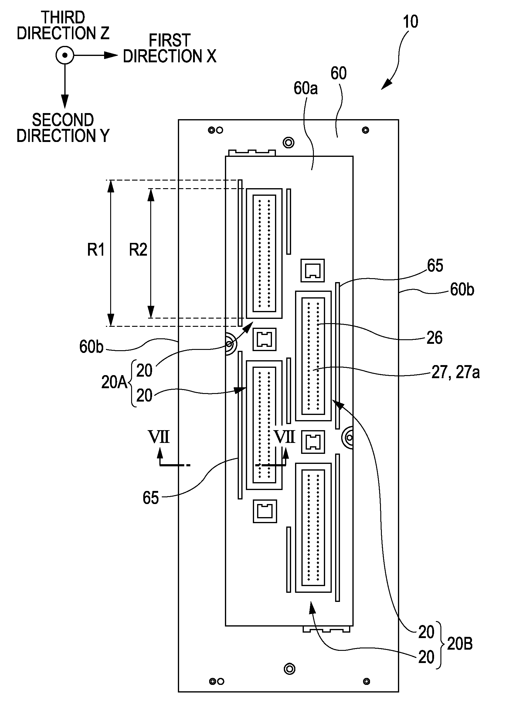
[0033]An embodiment of the invention will be described in detail. Hereinafter, an ink jet type recording head is one example of a liquid ejecting head and will also be simply referred to as a recording head.

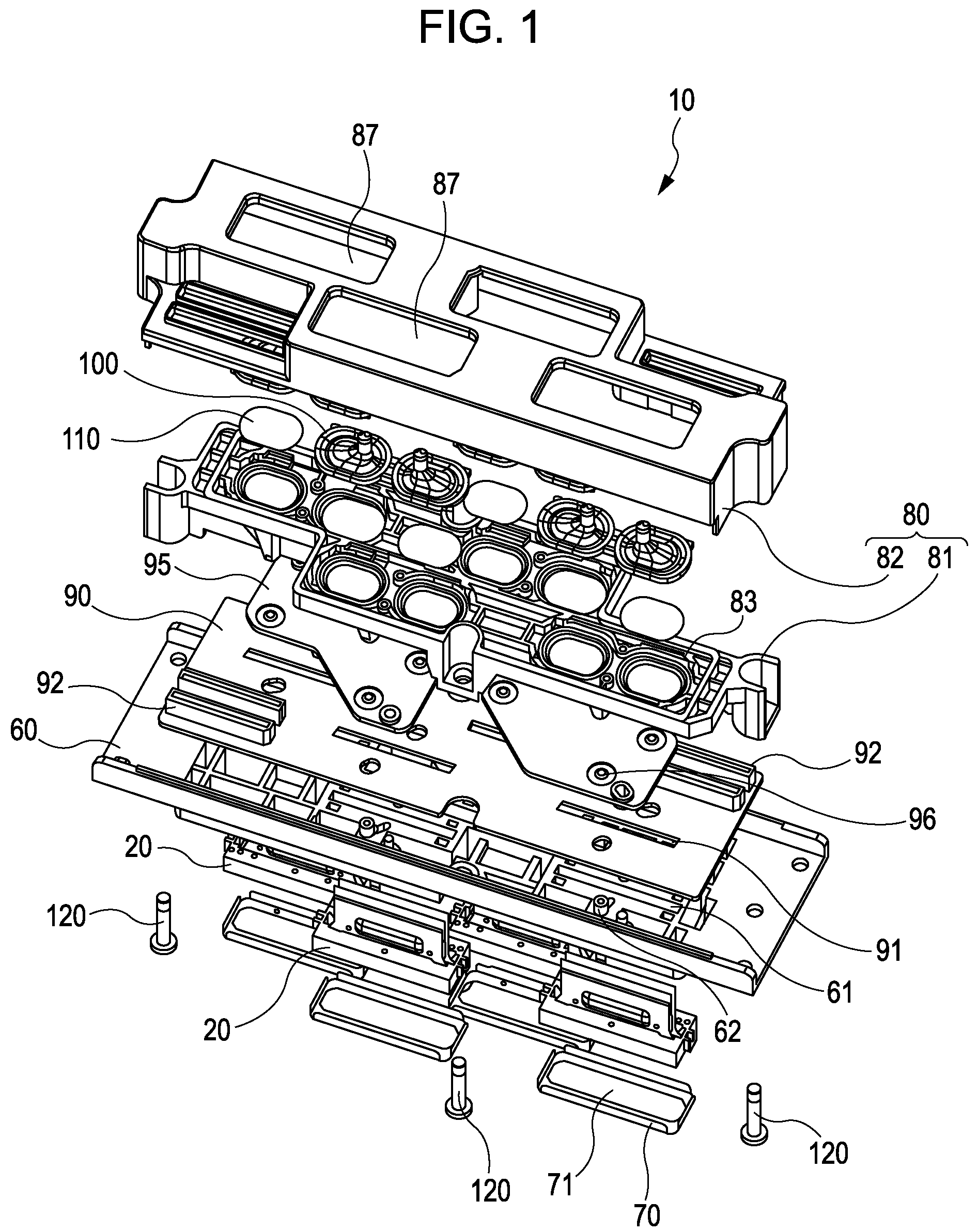
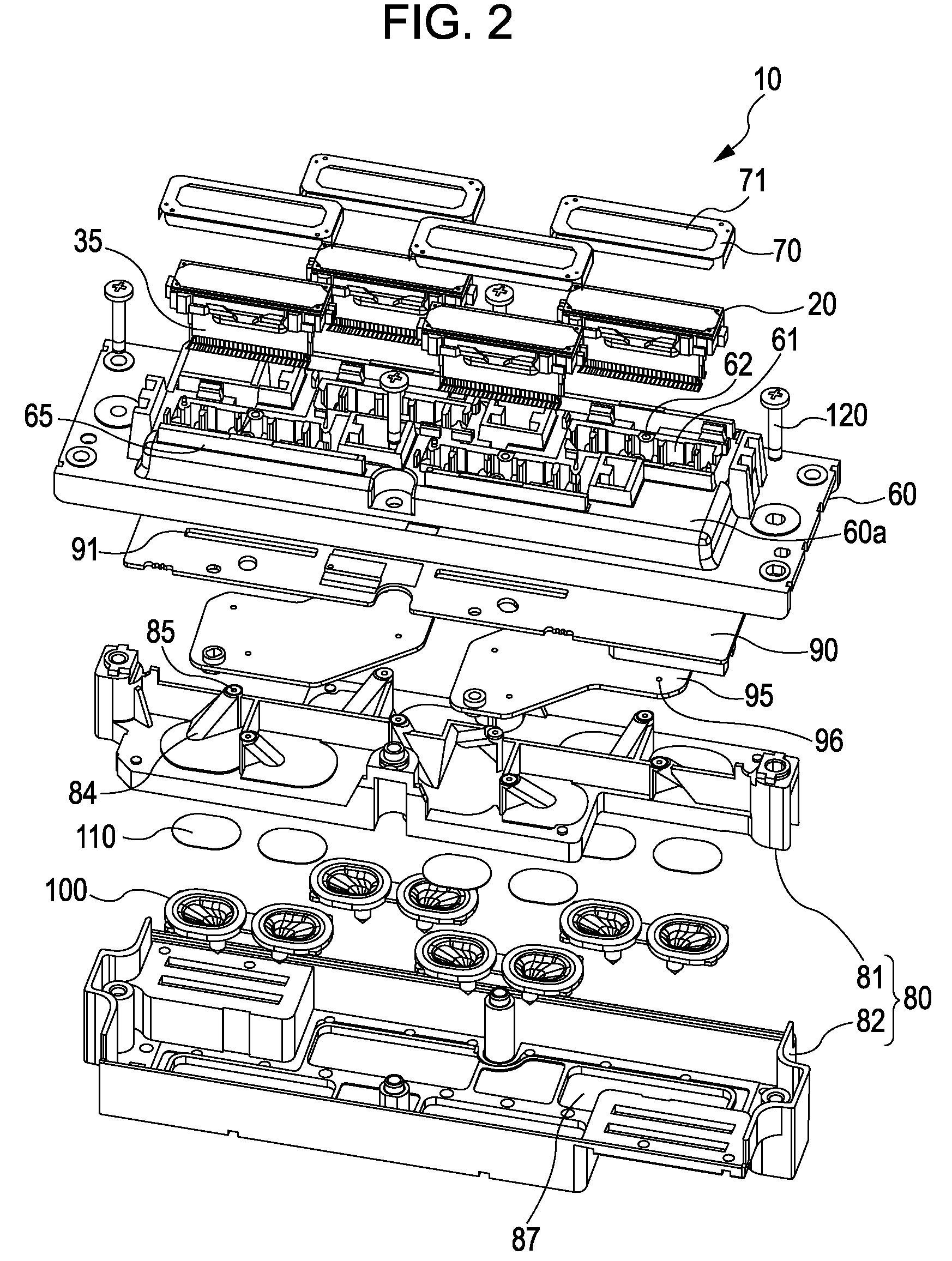
[0034]FIG. 1 is an exploded perspective view of the recording head related to this embodiment when viewed from one face side (the opposite side to a nozzle), FIG. 2 is an exploded perspective view of the recording head related to this embodiment when viewed from the other face side (the nozzle side), and FIG. 3 is a cross-sectional view of the recording head related to this embodiment.

[0035]As shown in FIGS. 1 and 2, a recording head 10 includes a plurality of head main bodies 20 which eject ink droplets, a case member 60 to which the head main bodies 20 are fixed, a flow path member 80 provided on the opposite surface side to the head main bodies 20 of the case member 60, and a circuit substrate 90 which is provided between the case member 60 and the flow path member 80.

[0036]On...

embodiment 2

[0087]The recording head 10 described in Embodiment 1 is mounted on an ink jet type recording apparatus that is one example of the liquid ejecting apparatus. FIG. 9 is a schematic perspective view showing an ink jet type recording apparatus that is one example of a liquid ejecting apparatus related to Embodiment 2 of the invention. In addition, the same component as that in Embodiment 1 is denoted by the same reference numeral and repeated explanation is omitted.

[0088]As shown in FIG. 9, an ink jet type recording apparatus I related to this embodiment is a so-called line type recording apparatus in which the recording head 10 is fixed and the recording sheet S such as paper that is a recording medium is transported, whereby printing is performed. The first direction X is a direction of relative movement of the recording head 10 with respect to the recording sheet S, and the second direction Y is a direction perpendicular to the first direction X.

[0089]Specifically, the ink jet type ...


PUM

PropertyMeasurementUnit
lengthaaaaaaaaaa
pressureaaaaaaaaaa
flexibleaaaaaaaaaa

Abstract

A liquid ejecting head includes head main bodies each having a nozzle plate having nozzle openings, and a case member to which the head main bodies are fixed, and moves relatively in a first direction with respect to a recording sheet, wherein a cover head which covers the side surfaces of the head main body and a peripheral border of the nozzle plate is provided at each head main body, a protective wall is provided for each head main body between an end portion in the first direction of the case member and the head main body, a range in a second direction of the cover head is included in a range in the second direction of the protective wall, and the protective wall is located further on the case member side than the nozzle plate in a third direction.

Description

BACKGROUND[0001]1. Technical Field[0002]The present invention relates to a liquid ejecting head which ejects liquid supplied from a liquid storage section to a head main body through a liquid supply path, from a nozzle, a liquid ejecting apparatus, and a method of manufacturing a liquid ejecting head.[0003]2. Related Art[0004]An ink jet type recording head that is a representative example of a liquid ejecting head is generally configured such that ink is supplied from an ink cartridge (a liquid storage section) filled with ink to a pressure generation chamber of a head main body through an ink flow path (a liquid flow path). Then, by imparting pressure to the inside of the pressure generation chamber by a pressure generation section such as a piezoelectric element, an ink droplet is ejected from a nozzle which communicates with the pressure generation chamber.[0005]As the specific configuration of the ink jet type recording head, for example, there is a recording head which is provi...

Claims


Application Information

Patent Timeline
Patent Type & Authority Patents(United States)
IPC IPC(8): B41J2/14
CPCB41J2/14233B41J2/1433B41J2/155B41J2202/19B41J2202/20B41J2002/14362Y10T29/49401
Inventor KOBAYASHI, HIROYUKIOWAKI, HIROSHIGESUZUKI, SHIGEKI
Owner SEIKO EPSON CORP
Why Eureka
Try Eureka