Optical image capturing system

Active Publication Date: 2013-12-03
LARGAN PRECISION
View PDF2 Cites 189 Cited by
  • Summary
  • Abstract
  • Description
  • Claims
  • Application Information

AI Technical Summary

Benefits of technology

[0008]In one practice of the present disclosure, the optical image capturing system in order from an object side to an image side, includes a first lens element, a second lens element, a third lens element, a fourth lens element, a fifth lens element, a sixth lens element and a seventh lens element. The first lens element with positive refractive power has a convex object-side surface. The second lens element has refractive power. The third lens element has refractive power. The fourth lens element has refractive power. The fifth lens element with refractive power has a convex image-side surface. The sixth lens element with positive refractive power has an object-side surface and an image-side surface which are both aspheric. The seventh lens element with negative refractive power has a concave image-side surface, and the concave image-side surface thereof changes from concave at a paraxial region to convex at a peripheral region, and an object-side surface and the image-side surface of the seventh lens element are both aspheric. When a curvature radius of the object-side surface of the seventh lens element is R13, a curvature radius of the image-side surface of the seventh lens element is R14, a focal length of the optical image capturing system is f, a focal length of the sixth lens element is f6, and a focal length of the seventh lens element is f7, the following relationships are satisfied:
[0009]According to another aspect of the present disclosure, an optical image capturing system includes, in order from an object side to

Problems solved by technology

However, the conventional optical systems cannot satisfy the requirements of high-end optical systems with camera functionalities.
A conventional optical image lens assembly with many lens elements is usually too bulky to have its size being miniaturized; therefore, it is not applicable to portable electronic products with a compact size.
An optical image lens assembly with five lens elements, such as

Method used


Image

  • Optical image capturing system
  • Optical image capturing system
  • Optical image capturing system

Examples


Example

1st Embodiment

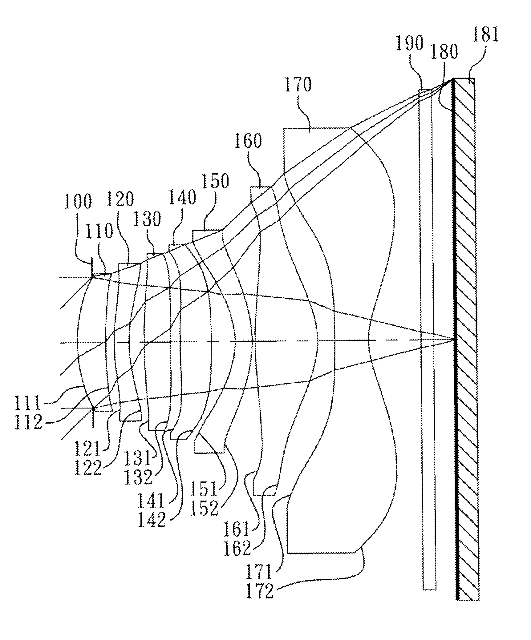
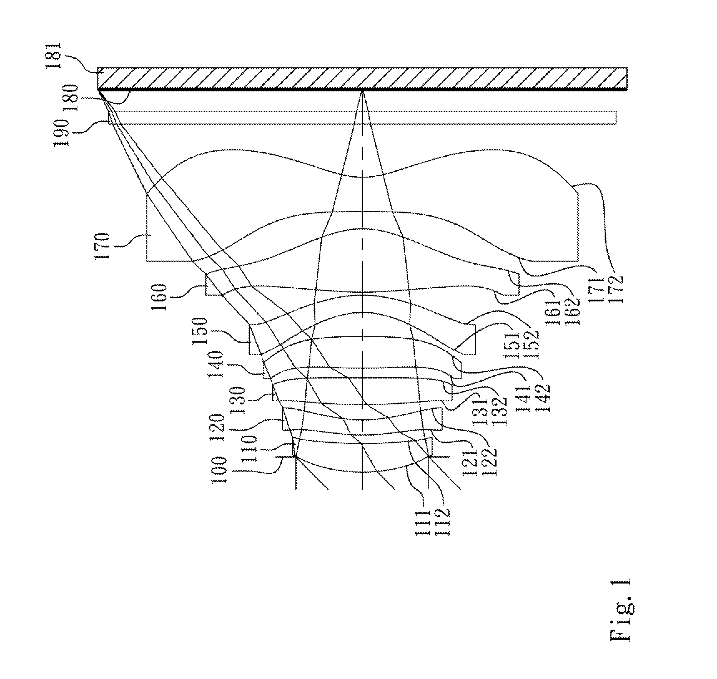
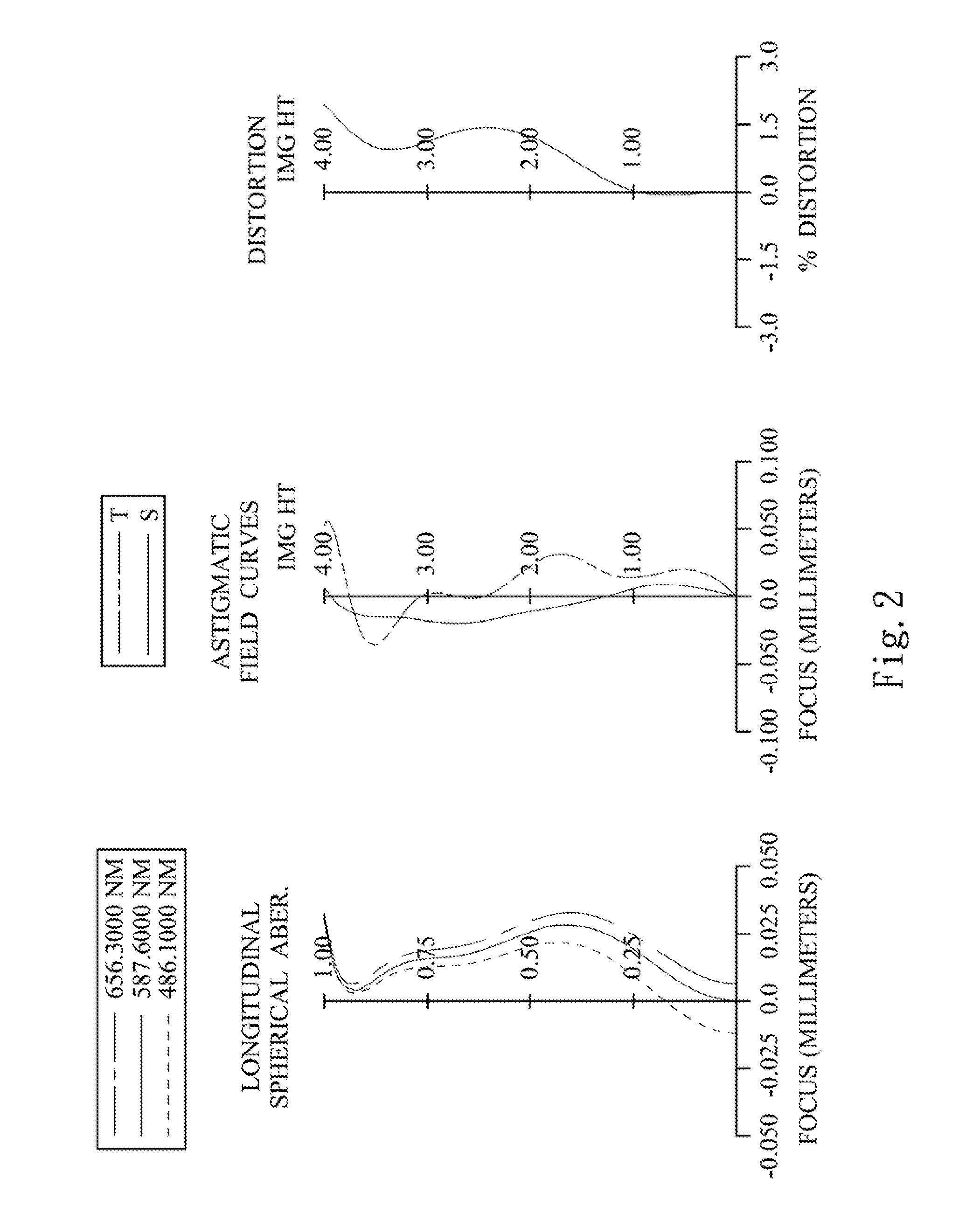
[0074]FIG. 1 is a schematic view of an optical image capturing system according to the 1st embodiment of the present disclosure. FIG. 2 shows, in order from left to right, spherical aberration curves, astigmatic field curves and a distortion curve of the optical image capturing system according to the 1st embodiment.

[0075]In FIG. 1, the optical image capturing system includes, in order from an object side to an image side, an aperture stop 100, a first lens element 110, a second lens element 120, a third lens element 130, a fourth lens element 140, a fifth lens element 150, a sixth lens element 160, a seventh lens element 170, an IR-cut filter 190, an image plane 180 and an image sensor 181.

[0076]The first lens element 110 with positive refractive power has a convex object-side surface 111 and a concave image-side surface 112, which are both aspheric, and the first lens element 110 is made of plastic material.

[0077]The second lens element 120 with negative refractive p...

Example

3rd Embodiment

[0123]FIG. 5 is a schematic view of an optical image capturing system according to the 3rd embodiment of the present disclosure. FIG. 6 shows, in order from left to right, spherical aberration cure es, astigmatic field curves and a distortion curve of the optical image capturing system according to the 3rd embodiment.

[0124]In FIG. 5, the optical image capturing system includes, in order from an object side to an image side, an aperture stop 300, a first lens element 310, a second lens element 320, a third lens element 330, a fourth lens element 340, a fifth lens element 350, a sixth lens element 360, a seventh lens element 370, an IR-cut filter 390, an image plane 380 and an image sensor 381.

[0125]The first lens element 310 with positive refractive power has a convex object-side surface 311 and a concave image-side surface 312, which are both aspheric, and the first lens element 310 is made of plastic material.

[0126]The second lens element 320 with negative refractive ...

Example

9th Embodiment

[0219]FIG. 17 is a schematic view of an optical image capturing system according to the 9th embodiment of the present disclosure. FIG. 18 shows, in order from left to right, spherical aberration curves, astigmatic field curves and a distortion curve of the optical image capturing system according to the 9th embodiment.

[0220]In FIG. 17, the optical image capturing system includes, in order from an object side to an image side, a first lens element 910, an aperture stop 900, a to second lens element 920, a third lens element 930, a fourth lens element 940, a fifth lens element 950, a sixth lens element 960, a seventh lens element 970, an 1R-cut filter 990, an image plane 980 and an image sensor 981.

[0221]The first lens element 910 with positive refractive power has a convex object-side surface 911 and a concave image-side surface 912, which are both aspheric, and the first lens element 910 is made of plastic material.

[0222]The second lens element 920 with negative refrac...


PUM


Abstract

An optical image capturing system includes, in order from an object side to an image side, a first lens element, a second lens element, a third lens element, a fourth lens element, a fifth lens element, a sixth lens element and a seventh lens element. The first lens element with positive refractive power has a convex object-side surface. The second through fifth lens elements all have refractive power. The fifth lens element has a convex image-side surface. The sixth lens element with positive refractive power has both of the object-side and image-side surfaces thereof being aspheric. The seventh lens element with negative refractive power has a concave image-side surface and both of the object-side and image-side surfaces thereof being aspheric. The image-side surface of the seventh lens element changes from concave at a paraxial region to convex at a peripheral region.

Description

RELATED APPLICATIONS[0001]The application claims priority to Taiwan Application Serial Number 101124430, filed Jul. 6, 2012, which is herein incorporated by reference.BACKGROUND[0002]1. Technical Field[0003]The present disclosure relates to an optical mage capturing system. More particularly, the present invention relates to a miniaturized optical image capturing system applicable to electronic products.[0004]2. Description of Related Art[0005]In recent years, with the popularity of mobile products with camera functionalities, a demand for optical system is increasing. A photosensitive sensor of a conventional optical system is typically a CCD (Charge-Coupled Device) or a CMOS (Complementary Metal-Oxide-Semiconductor) sensor. As advanced semiconductor manufacturing technologies have allowed a pixel size of sensors to be reduced and the optical systems have gradually evolved toward a field of higher megapixels, there is an increasing demand for better image quality.[0006]A convention...

Claims


Application Information

Patent Timeline
IPC IPC(8): G02B3/02G02B13/18
CPCG02B13/0045G02B9/64G02B3/04G02B13/18G02B13/0015G02B13/002H04N23/55G02B27/0025
Inventor TSAI, TSUNG-HANHUANG, HSIN-HSUAN
Owner LARGAN PRECISION
Why Eureka
Try Eureka