Fluid flow management system and associated methods

a flow management system and flow management technology, applied in the direction of fluid pressure measurement, liquid/fluent solid measurement, process and machine control, etc., can solve the problems of inability to efficiently pump when, inability to run longer in order, and small pumps to be able to pump at all. , to achieve the effect of optimizing the use of pumps, efficient wastewater delivery, and energy saving

Active Publication Date: 2013-12-03
DATA FLOW SYST
View PDF68 Cites 12 Cited by
  • Summary
  • Abstract
  • Description
  • Claims
  • Application Information

AI Technical Summary

Benefits of technology

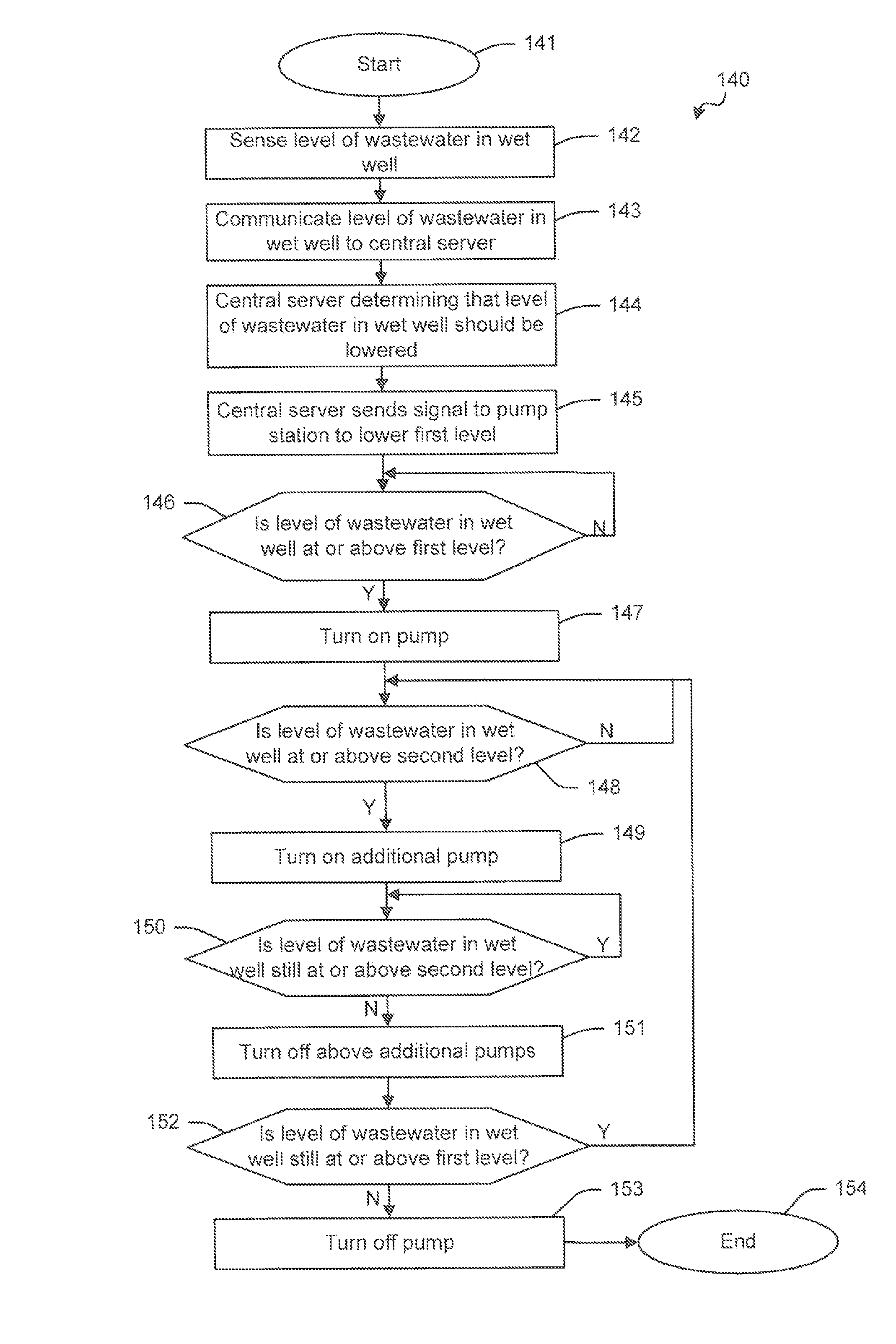
[0013]With the foregoing in mind, it is therefore an object of the present invention to provide a system to control fluid flow in a wastewater treatment system that can systematically manipulate pumps in wet wells to efficiently deliver wastewater to a wastewater treatment facility. It is also an object of the present invention to provide a system to control fluid flow that optimizes the use of pumps in a wastewater treatment system. It is further an object of the present invention to provide a system to control fluid flow that is energy efficient and that reduces wear on equipment and infrastructure, it is still further an object of the present invention to provide a system to control fluid flow that allows for an existing wastewater treatment plant to efficiently treat wastewater without the need to expand. It is yet another object of the present invention to provide a system that reduces peak flow times so as to enhance efficiency of a wastewater treatment plant. One other object of the present invention is to anticipate peak flow rates and manipulate the flow of wastewater to a wastewater treatment plant to prevent an overflow.
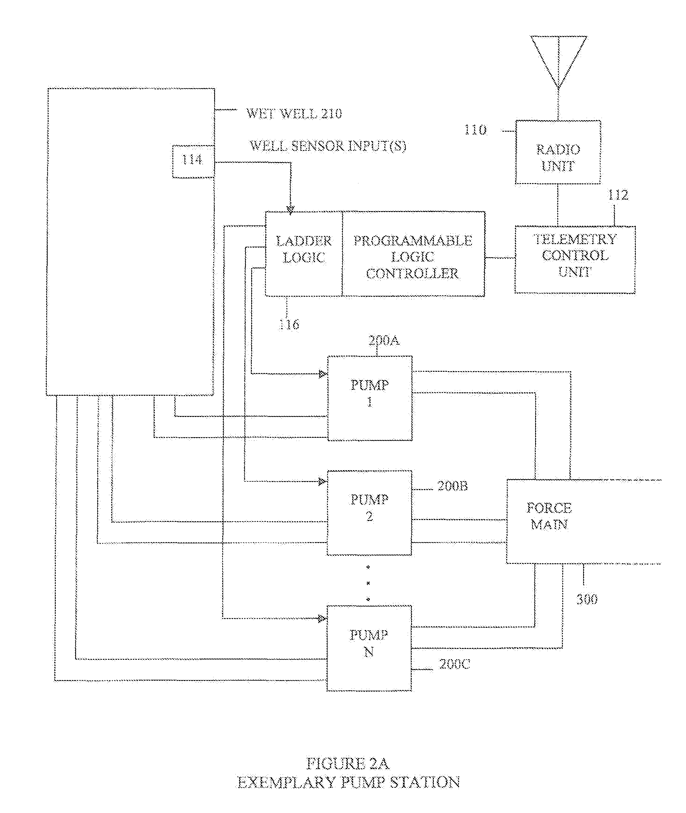
[0017]An embodiment of the present invention contemplates that wet well may include includes a pair of pumps. One of the pumps may be moved to the on position when the wastewater level in the wet well is sensed to be at or above the first level. The other one of the pair of pumps may be operated in the on position when the wastewater level in the wet well is sensed to be at or above a second level. The second level may be positioned at or below a level of an input into the wet well. Accordingly, the system of an embodiment of the present invention provides additional pumping capacity to prevent, or substantially reduce, fluid overflow within the wet well.

Problems solved by technology

Pumps cannot pump efficiently when pumping against higher pressures.
Smaller pumps may not be able to pump at all when more powerful pumps are dominating the force main.
This may cause pumps to run longer in order to accomplish their purpose.
This condition may result in drastically higher energy costs, increased wear and tear on pumps and mains, and a greater likelihood of failures of the pipes within the system which may, in turn, cause sewage spills.
When wastewater generation is at the lowest volume, e.g., in the middle of the right or, perhaps at mid-morning or mid-afternoon (when many users of a wastewater treatment system are either at work or at school), the majority of pumping stations are frequently dormant.
Plants designed to accommodate a daily average inflow run the risk of being incapable of handing those few peak hours of the day when most of the wastewater inflow occurs.
Surge basins can be costly to construct and can also be costly to maintain.
Further, there can be health risks associated with surge basins that can be associated with untreated wastewater being stored within the sure basin for various amounts of time.
Those wastewater treatment plants that are designed to accommodate the peak inflow hours sit idle for most of the day, since the peak inflows only occur during a few hours out of a 24-hour operational day.
Failure to provide sufficient capacity will likely result in pretreatment spills, damage to infrastructure which results in high repair costs and loss of service to customers, as well as possible damage to customer property.
Wastewater treatment plants that are overdesigned, i.e. designed to meet the peak flow periods, can be wasteful of taxpayer dollars during the initial construction, can result in higher maintenance and operation costs, and also result in higher energy usage.
Accordingly, although surge tanks address the issue of storing excess wastewater that needs to be treated, the problem of unmanageable flow of wastewater within a wastewater treatment system and, more particularly, within the pump stations and pipes that manage the flow of the wastewater to the wastewater treatment plants, remains unresolved.
Even more troubling, however, is the excess flow of wastewater through the force main of the wastewater treatment plant.
Another consequence of unmanaged flow is reduced efficiency in managing biological treatment material at the wastewater treatment plant.
High or irregular flow rates can lessen the efficiency of the treatment system and the quality of the treated effluent.
During this time, the utility may experience maintenance problems if the volume of wastewater through the main is not sufficient to carry with it solids and silt, if the flow of wastewater is so small relative to the pipe size that it fails to reach a velocity known as “scour speed,” solids may settle out of the liquid and accumulate in the bottom of the sewage mains.
When this occurs, expensive specialty vehicles typically known as vacuum trucks are employed to dean out sediment that accumulates in the sewage system.
Accordingly, with the above in mind, it is noted that wastewater collection and treatment systems often operate under conditions in which pumps operate inefficiently, causing increased energy cost and wear and tear on costly equipment.
It is further noted that peak flows into the treatment plant may result in accidental spillages and may impede the operational efficiency of the biological treatment processes utilized in the treatment plant.
The above description also indicates that there are times when flow is inadequate to keep the force mains free of sediment, requiring the use of expensive special purpose trucks.
In addition, the operational requirements of the various force mains may sometimes allows small pumps to run at the same time as larger pumps thereby causing the smaller pumps to operate against the higher pressure from the larger pumps resulting in considerable inefficiency in the operation of the smaller pumps.
Also, existing systems frequently encounter situations where the wet wells to do not get pumped down sufficiently and therefore begin to generate septic conditions with the accompanying unpleasant smells.

Method used


Image

  • Fluid flow management system and associated methods
  • Fluid flow management system and associated methods
  • Fluid flow management system and associated methods

Examples


Embodiment Construction

[0042]The present invention will now be described fully hereinafter with reference to the accompanying drawings, in which preferred embodiments of the invention are shown. This invention may, however, be embodied in many different forms and should not be construed as limited to the embodiments set forth herein. Rather, these embodiments are provided so that this disclosure will be thorough and complete, and will fully convey the scope of the invention to those skilled in the art. Those of ordinary skill in the art will realize that the following embodiments of the present invention are only illustrative and are not intended to be limiting in any way. Other embodiments of the present invention will readily suggest themselves to such skilled persons having the benefit of this disclosure.

[0043]FIGS. 1 through 12 are described in U.S. patent application Ser. No. 11 / 958,430, which claimed the benefit of U.S. Provisional Patent Application No. 60 / 870 / 862. The contents of each of these app...


PUM

PropertyMeasurementUnit
timeaaaaaaaaaa
flow rateaaaaaaaaaa
period of timeaaaaaaaaaa

Abstract

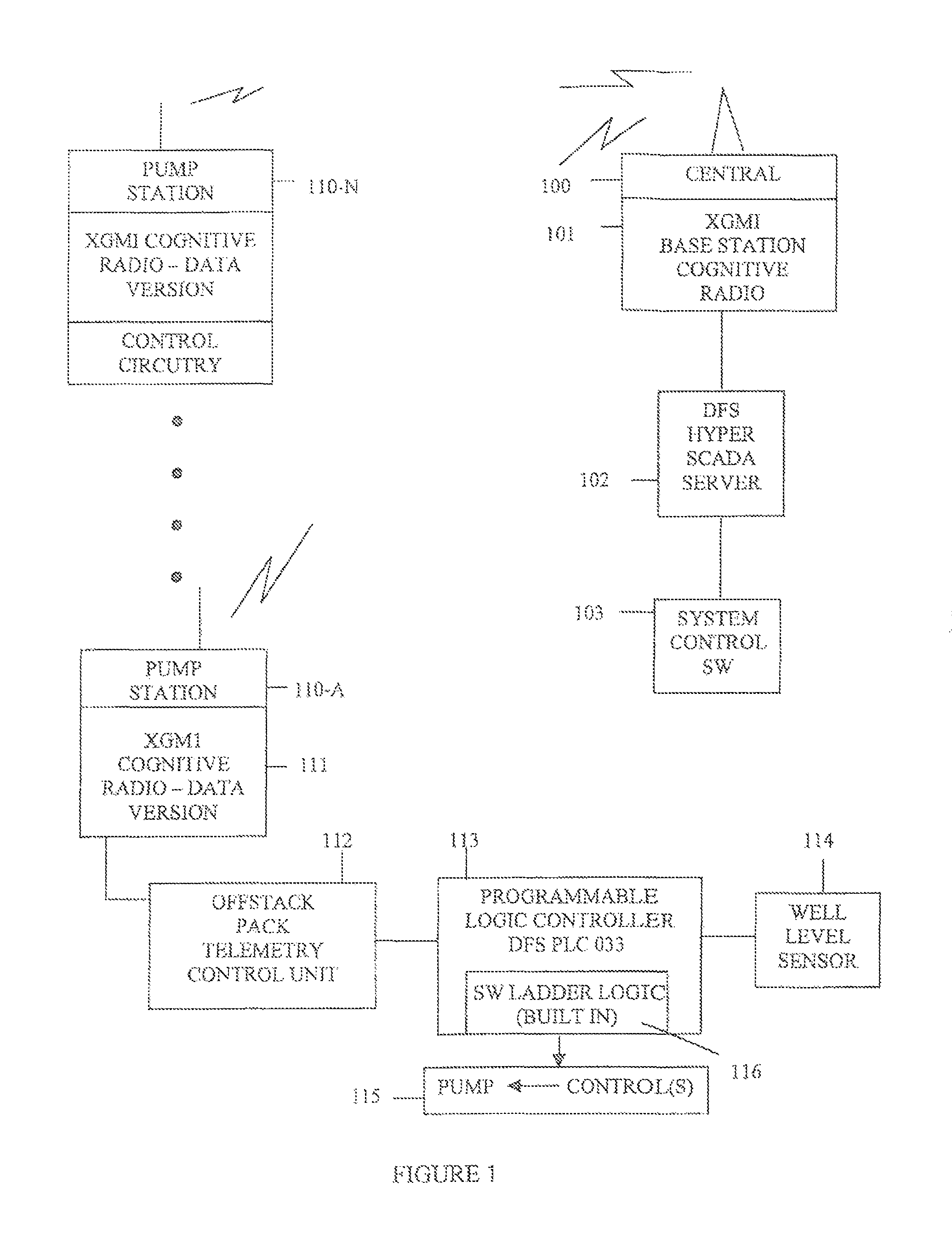
A system is provided to control fluid flow in a wastewater treatment system. The wastewater treatment system may include a wastewater treatment plant and a main that connects a plurality of pump stations to the wastewater treatment plant. Each of the plurality of pump stations may include a wet well and a pump carried by the wet well to pump the wastewater. The system may include a central server and a sensor in communication with the central server to sense a level of wastewater within the wet well. The pump may be moved to an on position when the level of the wastewater in the wet well is at or above a first level. The level of wastewater within the wet well may be systematically manipulated responsive to the central server to control the fluid flow in the wastewater treatment system. The system advantageously enhances fluid management in a wastewater treatment system, increases life span of the wastewater treatment plant, and saves energy associated with running pumps at the pump stations of the wastewater treatment system.

Description

RELATED APPLICATIONS[0001]The present application is a continuation in part application of U.S. patent application Ser. No. 11 / 958,430 titled Wastewater Collection Flow Management System and Techniques and filed on Dec. 18, 2007, which, in turn, claimed priority to U.S. Provisional Patent Application Ser. No. 60 / 870,862, filed on Dec. 20, 2006, titled Wastewater Collection Flow Management System, the entire contents of each of which are hereby incorporated into this application by reference.FIELD OF THE INVENTION[0002]The present invention relates, in general, to fluid transfer systems and, more particularly, to management of a both fluid flow and pumps used to move fluid through a fluid transfer system, and associated methods.BACKGROUND OF THE INVENTION[0003]In a wastewater collection service area, many pump stations often pump wastewater to a treatment facility or to a master pump station through a main. The main may sometimes be gravity fed, or may be under pressure, i.e., a forc...

Claims


Application Information

Patent Timeline
Patent Type & Authority Patents(United States)
IPC IPC(8): G05D7/00C02F1/00G05D11/00G05D9/00G01F1/12G11C19/00
CPCC02F1/008C02F3/006C02F2209/008C02F2209/42C02F2209/44Y10T137/2499Y10T137/2529Y10T137/2534Y10T137/2577Y10T137/2579
Inventor SMAIDRIS, THOMAS F.
Owner DATA FLOW SYST
Why Eureka
Try Eureka