

Ceiling fan
a fan and fan body technology, applied in the direction of machines/engines, stators, liquid fuel engines, etc., can solve the problems of reducing the number of components for transmitting driving torque and affecting the service life of the blade, so as to simplify the structure and reduce the number of components. , the effect of simplifying the structur
- Summary
- Abstract
- Description
- Claims
- Application Information
AI Technical Summary
Benefits of technology
Problems solved by technology
Method used
Image

Examples
first exemplary embodiment
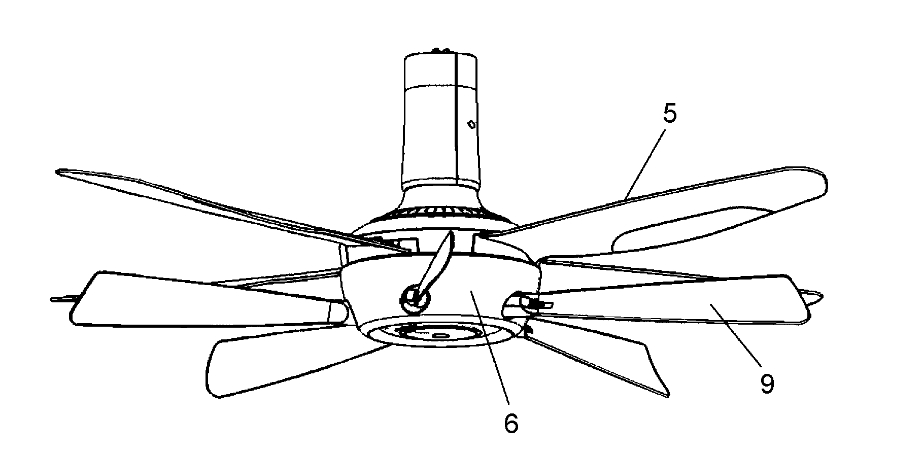
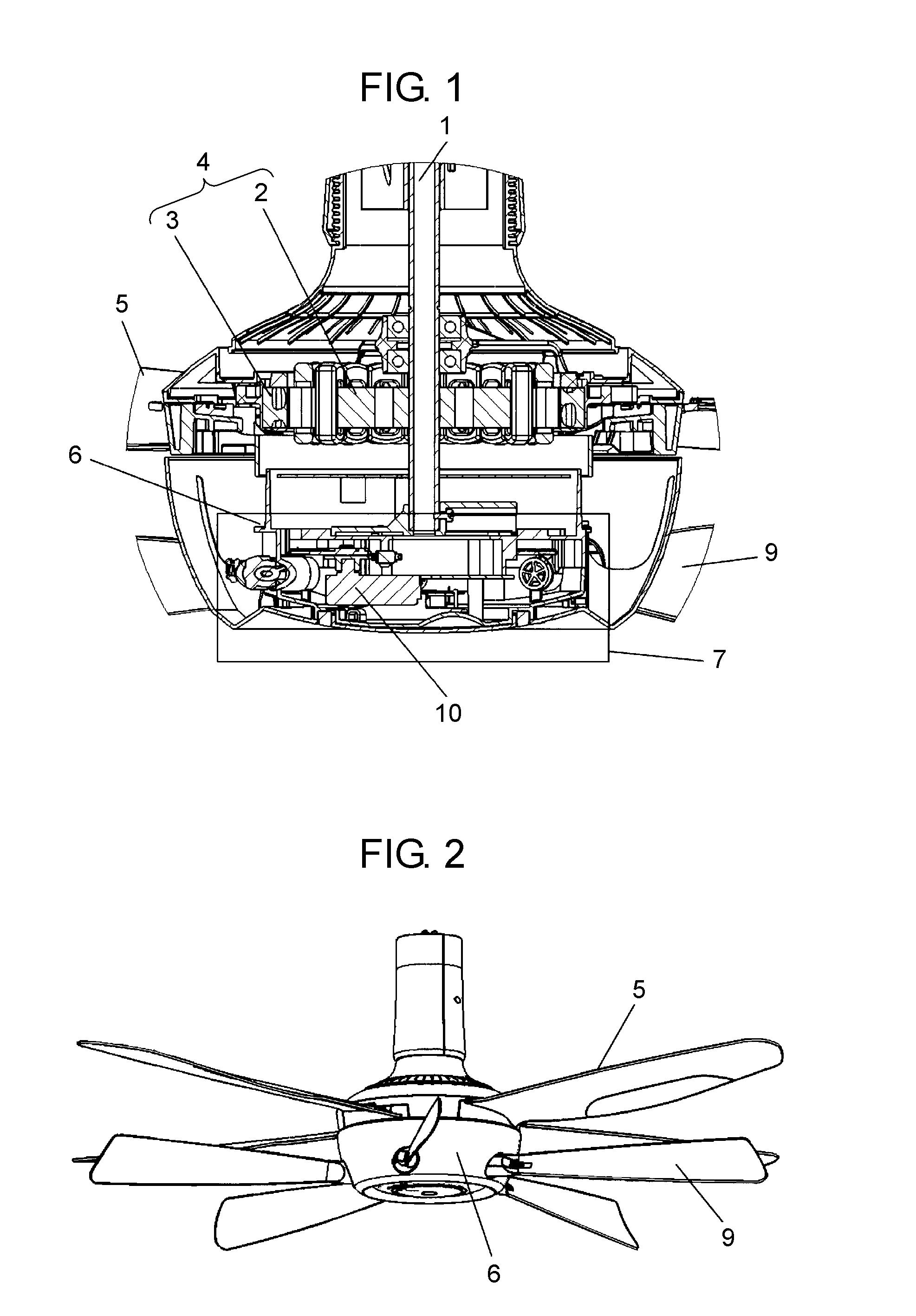
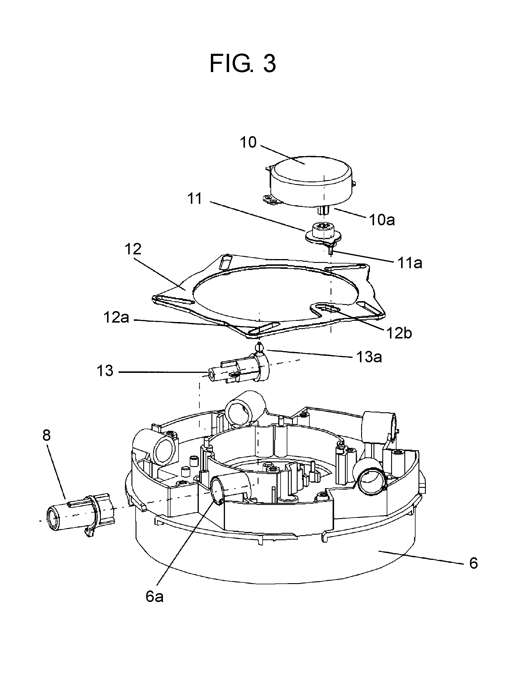
[0069]FIG. 1 is a sectional view showing a principal part of a ceiling fan in accordance with a first exemplary embodiment of the present invention. FIG. 2 is an external perspective view showing the ceiling fan. FIG. 3 is an exploded perspective view showing an angle changing unit of the ceiling fan when a back surface faces upward. FIG. 4 is an external perspective view showing an angle changing unit of the ceiling fan when a back surface faces upward. FIG. 5A is an enlarged view of a principal part showing an operation of a round cam of the angle changing unit of the ceiling fan. FIG. 5B is an enlarged view of a principal part showing an operation of a linkage and a stationary blade plate of the angle changing unit of the ceiling fan. FIG. 6 is a schematic sectional view showing the linkage of the ceiling fan. FIG. 7 is a sectional view of a principal part showing a relation between the linkage and a stationary blade holder of the ceiling fan. FIG. 8 is a view illustrating a rela...
second exemplary embodiment
[0084]FIG. 9 is an exploded perspective view showing a relation between a stationary blade plate and a movable plate portion in accordance with a second exemplary embodiment of the present invention. FIG. 10 is a sectional view of a principal part in assembly of a stationary blade holder and the stationary blade plate of the ceiling fan. FIG. 11A is an external perspective view before assembly of the stationary blade holder and the stationary blade plate of the ceiling fan. FIG. 11B is an external perspective view during assembly of the stationary blade holder and the stationary blade plate of the ceiling fan. FIG. 11C is an external perspective view after assembly of the stationary blade holder and the stationary blade plate of the ceiling fan. FIG. 12 is a sectional view of a principal part showing a state of a pressing spring when the stationary blade plate of the ceiling fan is assembled. FIG. 13 is a bottom view showing a relation between the total length of the blade plate and...
PUM
 Abstract
Description
Claims
Application Information