Broad band antenna

a wide-band antenna and communication system technology, applied in the direction of resonant antennas, antenna earthings, elongated active element feeds, etc., can solve the problems of remarkably changing the performance of the antenna, the size of the installation portion and the ground conductor

Active Publication Date: 2013-12-10
YOKOWO CO LTD
View PDF24 Cites 0 Cited by
  • Summary
  • Abstract
  • Description
  • Claims
  • Application Information

AI Technical Summary

Benefits of technology

[0011]In this case, Zo=120π•(μr / εr), with μr being a relative permeability of a propagation medium and εr being a relative permittivity of the propagation medium. In the case of a free space, μr=εr=1 and Zo becomes 120π. When a frequency f of a signal is higher than a cutoff frequency fc of the waveguide, the signal passes through this ridge waveguide. When the frequency f of the signal is overwhelmingly higher than the cutoff frequency fc, values of Zw and Ze become 120π like Zo in a free space. A cutoff frequency fc of the ridge waveguide is lower than that of an ordinary rectangular waveguide having the same cross-section size, for instance. Therefore, it becomes possible to realize an antenna in which wide band property is maintained while lowering a usable frequency. Also, a surface portion that is similar to the ridge element portion is included, so a matching range is broadened as compared with a case where, for instance, a wire is wound. In other words, it also becomes possible to suppress a mismatch at a feeder terminal while achieving a function as an electromagnetic wave radiator. At the time of designing and production, it is sufficient that consideration is given only to the lowest frequency whose use is planned, which facilitates mass production and also realizes cost reduction. Accordingly, the wide band antenna according to the present invention operates in an operation mode, such as an operation mode of a high pass filter, in which when the cutoff frequency fc is determined, all frequencies f that are significantly higher than the cutoff frequency fc are passed.
[0013]The ground portion is connected directly with an external ground conductor. Since the ground portion is originally maintained to the ground potential, the ground portion is connected directly with the external ground conductor, to thereby suppress a variation in the used frequency. The configuration and size of the external ground conductor can be arbitrarily set. That is, it is possible to realize the antenna that is not affected by the installation portion.
[0015]It is preferred that at least one of the ridge element portion and the ground portion be formed in arc or substantially arc. Such a configuration increases the upper limit of the available frequency unboundedly as compared with the configurations having other than arc or substantially arc, thereby making it possible to provide a remarkable wide band property. The ridge element portion is integrated with the adjustment element portion for fine adjustment of the band from the viewpoint that excellently maintains the wide band property.
[0017]In the wide band antenna, when electricity from the feeder terminal is fed to a center portion of the ridge element portion, there occur multiple mode waves that are symmetric with the site as a center. In the case of the ridge waveguide, an electric field strength of a passing electromagnetic wave becomes the maximum at a center (TE10) of the ridge portion, so even when the ridge element portion is given a one base end configuration, the characteristics themselves of a high pass filter do not differ from those in the case of a both base end configuration to be described later. It becomes possible to reduce a size thereof by a degree corresponding to the one base end configuration.
[0021]According to the present invention, there can be provided the wide band antenna having an ultra wide band property that the available lowest frequency is provided. As described above, it has been difficult to widen the band in the antenna having the ground portion. However, as in the present invention, with the provision of the opening structure of the ridge waveguide, the band can be widened.

Problems solved by technology

The conventional mobile terminal antenna had problems inherent therein such as its installation portion and a size of a ground conductor, that is, a ground portion.
Since the conventional wide band antenna (broad band antenna) is configured by the ground portion and an emission element portion in cooperation, there arise such problems that it is impossible to realize the wide band property, the antenna performance is remarkably changed with a change in installation portion of the antenna or a difference in the size of the ground portion.

Method used


Image

  • Broad band antenna
  • Broad band antenna
  • Broad band antenna

Examples


first embodiment

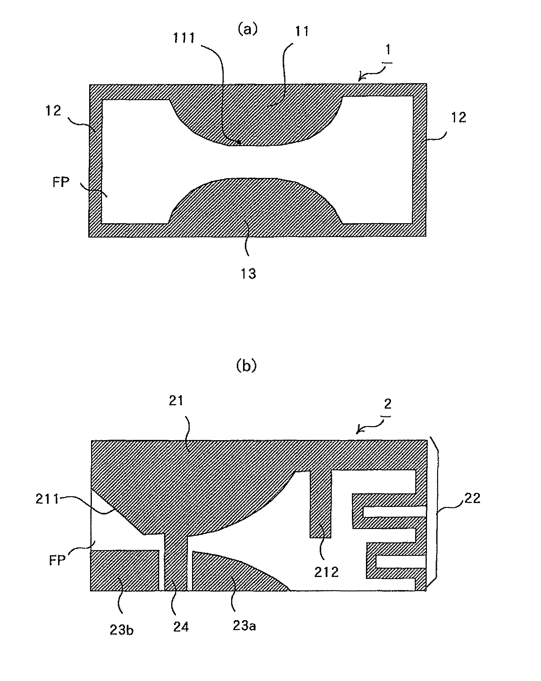
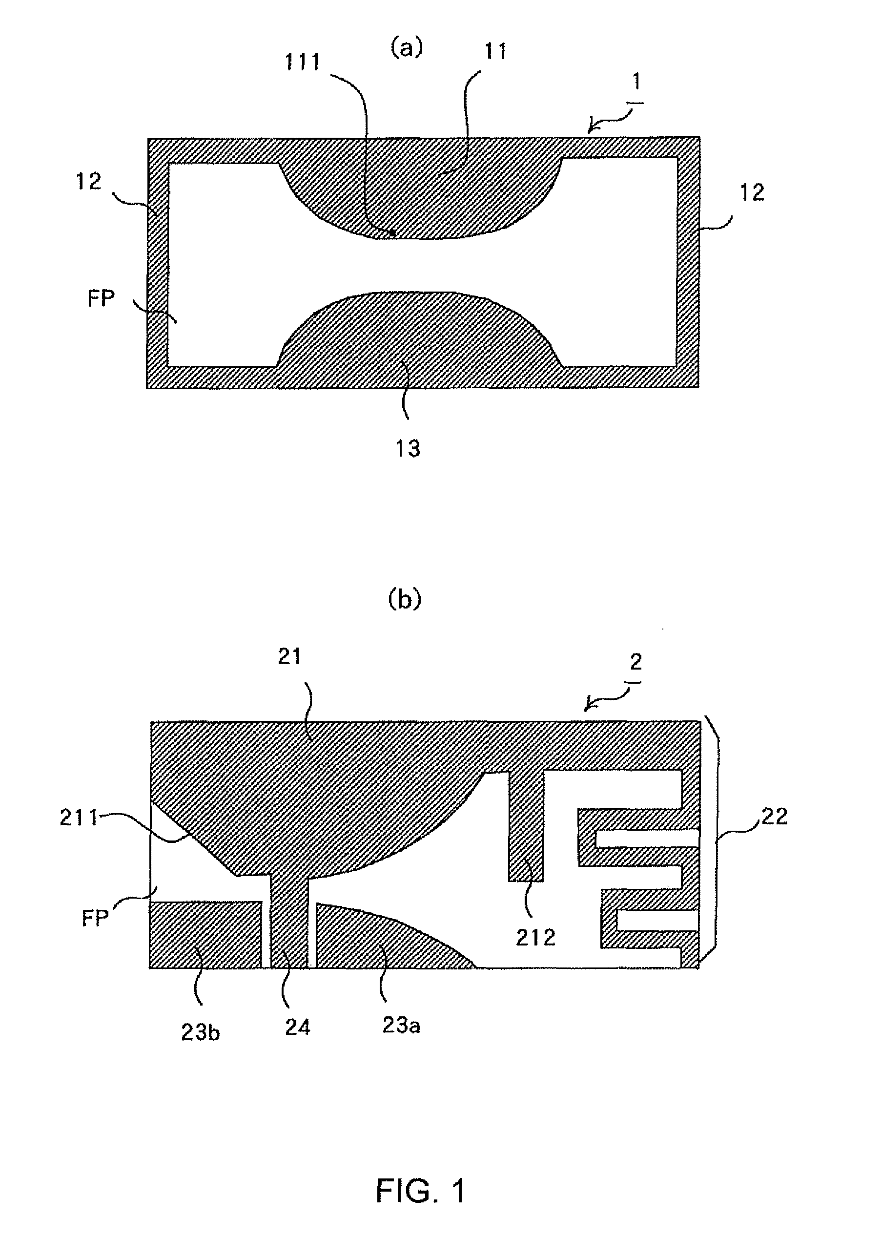
[0053]Hereinafter, a description will be given of a mode example when the present invention is implemented as a UWB antenna of a wide band used in a UWB communication. In this example, there is shown an example in which the present invention is applied to a planar wide band antenna having an opening cross section structure of a double cylinder ridge waveguide.

[0054]FIG. 1(a) shows a basic pattern of an antenna element included in a wide band antenna according to the present invention. A wide band antenna 1 is configured by provision of an antenna element having an opening cross section structure of the double cylinder ridge waveguide on a planar substrate FP that is made of, for example, resin. The antenna element is made of a metal that is high in conductivity, for example, copper.

[0055]The antenna element is structured by both base ends that are symmetrical about a portion that is highest in the height of the ridge portion of the ridge waveguide in the opening cross section struct...

second embodiment

[0094]In a second embodiment, a description will be given of a mode example in which the present invention is implemented as the wide band antenna that is used in the radio LAN communication and the UWB communication. In this example, the present invention is applied to the wide band antenna having the opening cross section structure of the double cylinder ridge waveguide.

[0095]FIG. 21(a) shows an example of a wide band antenna 51 that is suitable for use in the mobile terminal. The antenna element of the wide band antenna 51 has a ridge element portion 52, a first radiation element portion 53, ground portions 54a and 54b, a feeder wire 55, an erection element portion 56, and a second radiation element portion 57.

[0096]The ridge element portion 52 is configured in such a manner that a portion corresponding to one ridge portion of the double cylinder ridge waveguide is cut at an eccentric position where the larger amount of ridge portion remains from the center line in the height dir...


PUM


Abstract

Provided is a wide band antenna having ultra-wide band and high performance at a low cost. An antenna element constituting a part of an opening cross section structure of a double cylinder ridge waveguide is spread on a plane. The antenna element has a ridge element portion (21) for adjusting antenna characteristic corresponding to a ridge portion and a radiation element portion (22) for electromagnetic wave radiation. Substantially at a leading end portion of the ridge element portion (21), a feeder terminal (24) is formed. Ground portions (23a and 23b) are maintained at a ground potential and the feeder terminal (24) is guided to an outside as a coplanar waveguide.

Description

CROSS-REFERENCE TO RELATED APPLICATIONS[0001]This application is a 371 of PCT / JP2006 / 315788 filed Aug. 3, 2006, which claims priority under 35 U.S.C. 119 from JAPAN 2005-227154 filed on Aug. 4, 2005, the contents of which are incorporated herein by reference.TECHNICAL FIELD[0002]The present invention relates to an antenna for a wide band communication system such as an ultra wide band (UWB) and a radio local area network (LAN), and more particularly, to a wide band antenna suitable as an antenna for a mobile terminal.BACKGROUND ART[0003]In recent years, a wide band communication system in which a UWB is applied and a radio LAN have been applied in diverse fields. For example, mobile terminals such as a personal computer (hereinafter, referred to as “PC”) having a communication function owing to the UWB or the radio LAN, a cellular phone, and a personal digital assistance (PDA) have arrived.[0004]Because various band frequencies are used in the UWB, the UWB antenna having a band as w...

Claims


Application Information

Patent Timeline
Patent Type & Authority Patents(United States)
IPC IPC(8): H01Q1/38H01Q13/00
CPCH01Q1/22H01Q9/42H01Q5/378H01Q19/26H01Q5/25H01Q13/10H01Q13/08H01Q1/38
Inventor GE, JUNXIANGYANAGISAWA, WASUKEHORIE, RYO
Owner YOKOWO CO LTD
Why Eureka
Try Eureka