Method for providing an energy assisted magnetic recording (EAMR) head

Active Publication Date: 2013-12-17
WESTERN DIGITAL TECH INC
View PDF8 Cites 155 Cited by
  • Summary
  • Abstract
  • Description
  • Claims
  • Application Information

AI Technical Summary

Problems solved by technology

More specifically, aligning the laser 30 and optical component 32 to the desired position with respect to the conventional transducer 28 is time consuming and prone to error.
The throughput and yield of a manufacturing for f

Method used


Image

  • Method for providing an energy assisted magnetic recording (EAMR) head
  • Method for providing an energy assisted magnetic recording (EAMR) head
  • Method for providing an energy assisted magnetic recording (EAMR) head

Examples


Embodiment Construction

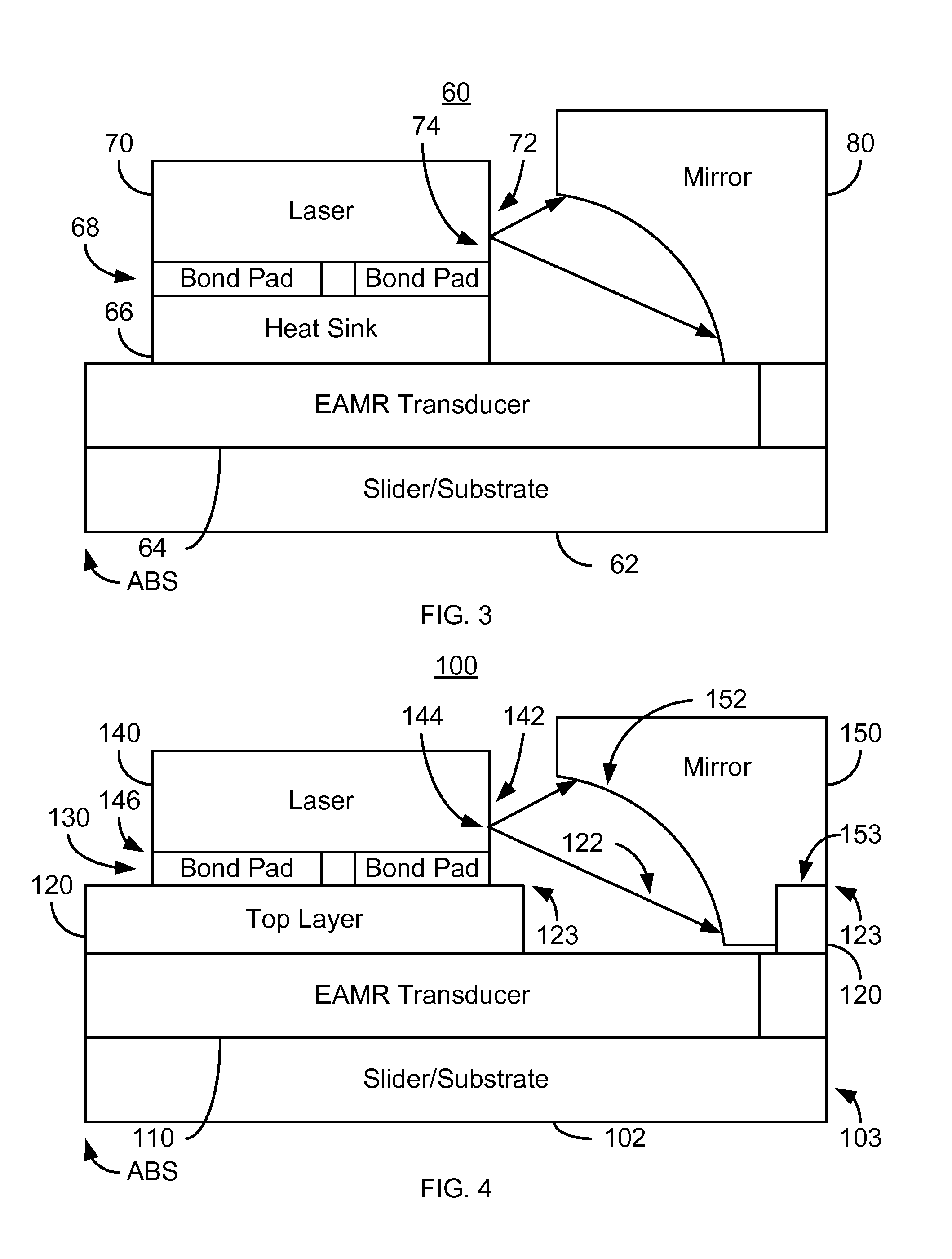
[0017]FIG. 3 is a diagram depicting a side view of a more recently developed EAMR head 60. For clarity, FIG. 3 is not to scale. The EAMR head 60 includes a slider 62, EAMR transducer 64, heat sink 66, bond pads 68, laser 70, and mirror 80. The heat sink 66 and mirror 80 are both affixed to the top of the EAMR transducer 62 / slider 62. The EAMR head 60 may include read transducer(s) (not shown) and other components. The slider 62 is part of the substrate on which the EAMR transducer 64 resides. The EAMR transducer 64 is used to write to a media (not shown) oriented in proximity to the air-bearing surface (ABS). The heat sink 66 to which laser 70 is bonded via bond pads 68 assists in cooling the laser 70. The laser 70 has a light emitting surface 72 from which light is emitted at region 74. Light from the laser 70 is reflected by the mirror 80 and provided to the EAMR transducer 64. In FIG. 3, the light emitted from the laser 70 and incident on the mirror 80 is shown by arrows. However...


PUM

PropertyMeasurementUnit
Distanceaaaaaaaaaa
Electrical conductoraaaaaaaaaa
Distanceaaaaaaaaaa

Abstract

A method and system for providing an energy assisted magnetic recording (EAMR) head are described. The method and system include providing a slider, an EAMR transducer coupled with the slider, and a top layer on the slider. The top layer includes a mirror well therein and has a substantially flat top surface. The method and system further includes providing a laser including a light-emitting surface and providing a mirror optically coupled with the laser. The laser is coupled to the top surface of the top layer external to the mirror well. The mirror has a bottom surface and a reflective surface facing the light-emitting surface of the laser. A portion of the bottom surface of the mirror is affixed to the top surface of the top layer. A portion of the mirror resides in the mirror well.

Description

BACKGROUND[0001]FIG. 1 depicts a side view of portion of a conventional energy assisted magnetic recording (EAMR) disk drive 10. The conventional EAMR disk drive 10 includes a recording media 12, a conventional slider 20, and a conventional laser diode 30 that are typically attached to a suspension (not shown). The conventional slider 20 has a leading edge 22, a trailing edge 26, and a back side 24. Other components that may be part of the conventional EAMR disk drive 10 are not shown. The conventional slider 20 is typically attached to the suspension at its back side 24. A conventional EAMR transducer 28 is coupled with the slider 20.[0002]The laser diode 30 is coupled in proximity to the EAMR transducer 28 on the trailing edge 26 of the slider 20. Light from the conventional laser diode 30 is provided substantially along the optic axis of the conventional laser diode 30 to the trailing edge 26 of the slider 20. Light may be provided via an optical component 32. Although shown as a...

Claims


Application Information

Patent Timeline
IPC IPC(8): G11B5/127H01R31/00
CPCG11B5/102G11B5/105G11B2005/0021Y10T29/49052Y10T29/49039Y10T29/49048Y10T29/49044Y10T29/49043Y10T29/49046
Inventor WANG, LEIWAN, DUJIANG
Owner WESTERN DIGITAL TECH INC
Why Eureka
Try Eureka