Device and method for increasing the wind load resistance and disengage-ability of overhead roll-up doors

a technology for overhead roll-up doors and wind load resistance, which is applied in the direction of door/window protective devices, curtain suspension devices, shutters/movable grilles, etc., can solve the problems of increasing wind load, dramatically increasing the total load of doors, and increasing wind load, so as to increase the wind load resistance of overhead roll-up doors and enhance the ability of doors and their components to disengage. , the effect of increasing the wind load resistan

Active Publication Date: 2013-12-17
RYTEC CORP
View PDF35 Cites 7 Cited by
  • Summary
  • Abstract
  • Description
  • Claims
  • Application Information

AI Technical Summary

Benefits of technology

[0011]The present invention is directed to a device and method for increasing wind load resistance of an overhead roll-up door, particularly when the door panel is in a substantially closed position, while enhancing the ability of the door and its components to disengage from the side columns and / or vertical panel guide assembly if the door or its components are impacted by a force when the door is opening or closing.
[0013]According to another aspect of the invention, in order to enhance the stiffness and wind load resistance of the door panel, attached proximate a leading or bottom edge of the door panel is a bottom bar having a greater stiffness, and in some embodiments a greater thickness, than the door panel. The bottom bar may be configured to have a width extending transversally across the leading or bottom edge of the door panel a second distance less than the first distance between the side columns to prevent the engagement of the bottom bar and the side columns as the door panel opens, closes, or stops in a fully or partially closed position.
[0014]According to still another aspect of the invention, in order to further increase the wind load resistance of the door as the door panel approaches a substantially closed position, bottom bar guides capable of engaging and receiving at least a portion of the bottom bar may be disposed proximate a lower portion of the opening. The bottom bar guides may include a front body, a back body, and a vertical channel there between for receiving and engaging at least a portion of the bottom bar. The bottom bar guides may be made of a rigid material, which when engaging at least a portion of the bottom bar, holds the bottom bar in place and prevents it from disengaging therewith in the event the door panel experiences a high wind load or air pressure.
[0015]According to yet another aspect of the invention, the bottom bar guides may extend vertically from a lowermost portion of the opening a desired distance less than the vertical guides, and in preferred embodiments a distance less than or equal to 24 inches. The vertical height of 24 inches for the bottom bar guides is preferred because a distance of 24 inches between the bottom bar and lowermost portion of the opening provides enough room for the wind and air pressure to escape underneath the door panel to help insure that the bottom bar does not deviate too far from the closing path and can easily engage the bottom bar guides as the door closes. Extending the bottom bar guides a shorter vertical distance also helps prevent the locking of bottom bar to facilitate the disengagement of the door panel and bottom bar from the vertical guides if either are impacted by an object during a substantial portion of the opening and closing sequence.
[0020]According to another aspect of the invention, the bottom bar guides may further include a connector for holding the first and second faces of the bottom bar guides together, enhancing the rigidity of the bottom bar guides, and therefore enhancing the wind load resistance of the door when the door panel is in at least a substantially closed position. The connector may be, for example, a bolt or screw, which extends through the entire bottom bar guides and prevents the bottom bar guides from deforming from pressure which is applied by the bottom bar on the bottom bar guides as a result of wind or air pressure on either side of the door panel.
[0022]As should be appreciated by those having ordinary skill in the art, while narrower than the distance of the vertical guides, the width of the bottom bar with or without end tabs should remain sufficient to allow at least a portion of the bottom bar to engage the bottom bar guides when the door panel is in at least a substantially closed position. In order to accomplish this, the bottom bar guides should be disposed between the guide assemblies. Configuring the door assembly in this manner allows the bottom bar to travel between the open and closed positions, substantially free of any encumbrances, eliminating any engagement between the bottom bar and the guide assemblies, thereby minimizing any damage to the door panel, the bottom bar, and the guide assemblies resulting from an impact from an object. Since the total width of the bottom bar, including any end tabs, is less than the distance between the guide assemblies, the bottom bar and any associated end tabs may be made more rigid than standard bottom bars because the bottom bar does not have to disengage from the guide assemblies if the bottom bar or door panel is impacted. As should be appreciated, increasing the rigidity of the bottom bar increases the wind load resistance capabilities of the door when the bottom bar is engaged with the bottom bar guides when the door panel is in the substantially closed position.

Problems solved by technology

Wind load when the door is in a substantially closed or fully closed position is particularly problematic, because as is known in the art, the wind load increases as the door panel approaches a fully closed position.
As more of the door panel is exposed, a greater surface area of the door panel may become “impacted” by the wind creating the load, thereby dramatically increasing the total load on the door.
In addition to having to account for wind load resistance, these doors may also be installed in high-traffic areas with the potential to be impacted by objects when the door is opening or closing—a necessitating that the door panel maintain a particular level of breakaway-ability in response to such an impact.
If these tabs are too flexible they may not hold up under high winds, i.e. may lead to the door becoming disengaged, even in a substantially closed position, from wind or air pressure.
Conversely, if the tabs are too rigid, the bottom bar, side columns, or door panel could be damaged if the bottom bar or door panel is impacted by an object, inasmuch as the tabs may fail to release from the side columns upon impact.
This inverse relationship can make door design difficult, especially in high wind or high pressure / impact areas—particularly where substantial traffic frequently passes through the opening blocked and unblocked by the door panel.
In doors where engagement between the tabs and side columns is relied on to provide much of the wind load resistance, the breaking away of the tabs may lead to the door having unsatisfactory wind load resistance capabilities and creating unwanted blow out resulting from normal or even light wind loads.
If impacted, however, the sheer pins may break, allowing the bottom bar to bend at the notch and succumb to external forces, for example wind, even when in the substantially closed position.

Method used


Image

  • Device and method for increasing the wind load resistance and disengage-ability of overhead roll-up doors
  • Device and method for increasing the wind load resistance and disengage-ability of overhead roll-up doors
  • Device and method for increasing the wind load resistance and disengage-ability of overhead roll-up doors

Examples


Embodiment Construction

[0036]While the present invention is susceptible of embodiment in many different forms, there is shown in the drawings and will herein be described in detail, preferred embodiments of the invention with the understanding that the present disclosure is to be considered as an exemplification of the principles of the invention and is not intended to limit the broad aspect of the invention to the embodiments illustrated.

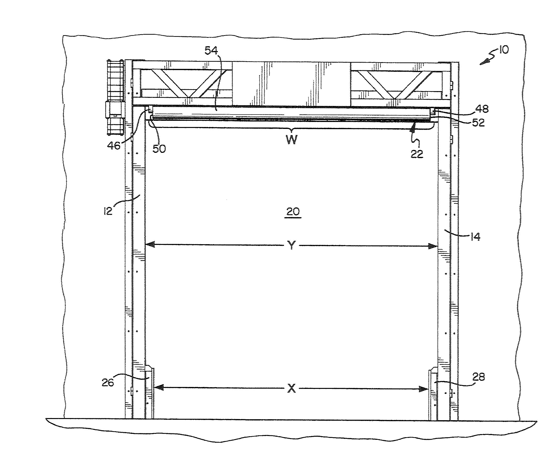
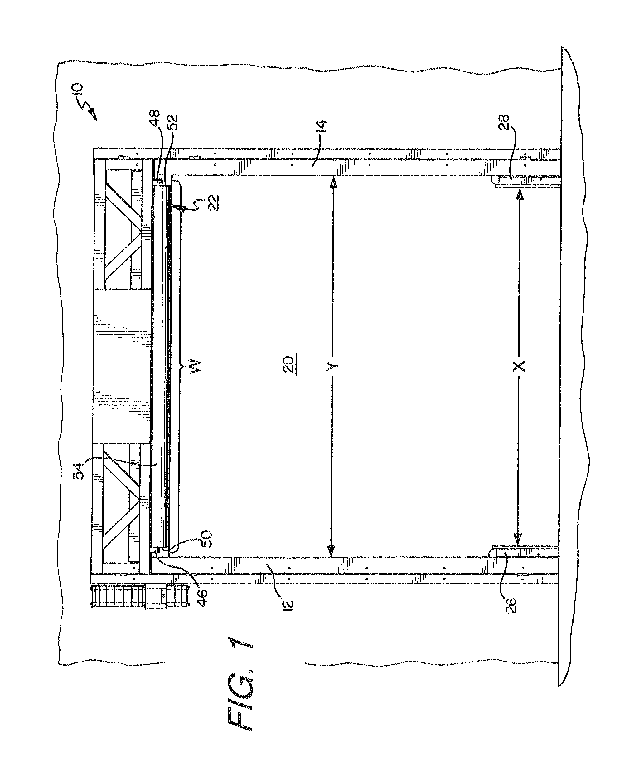
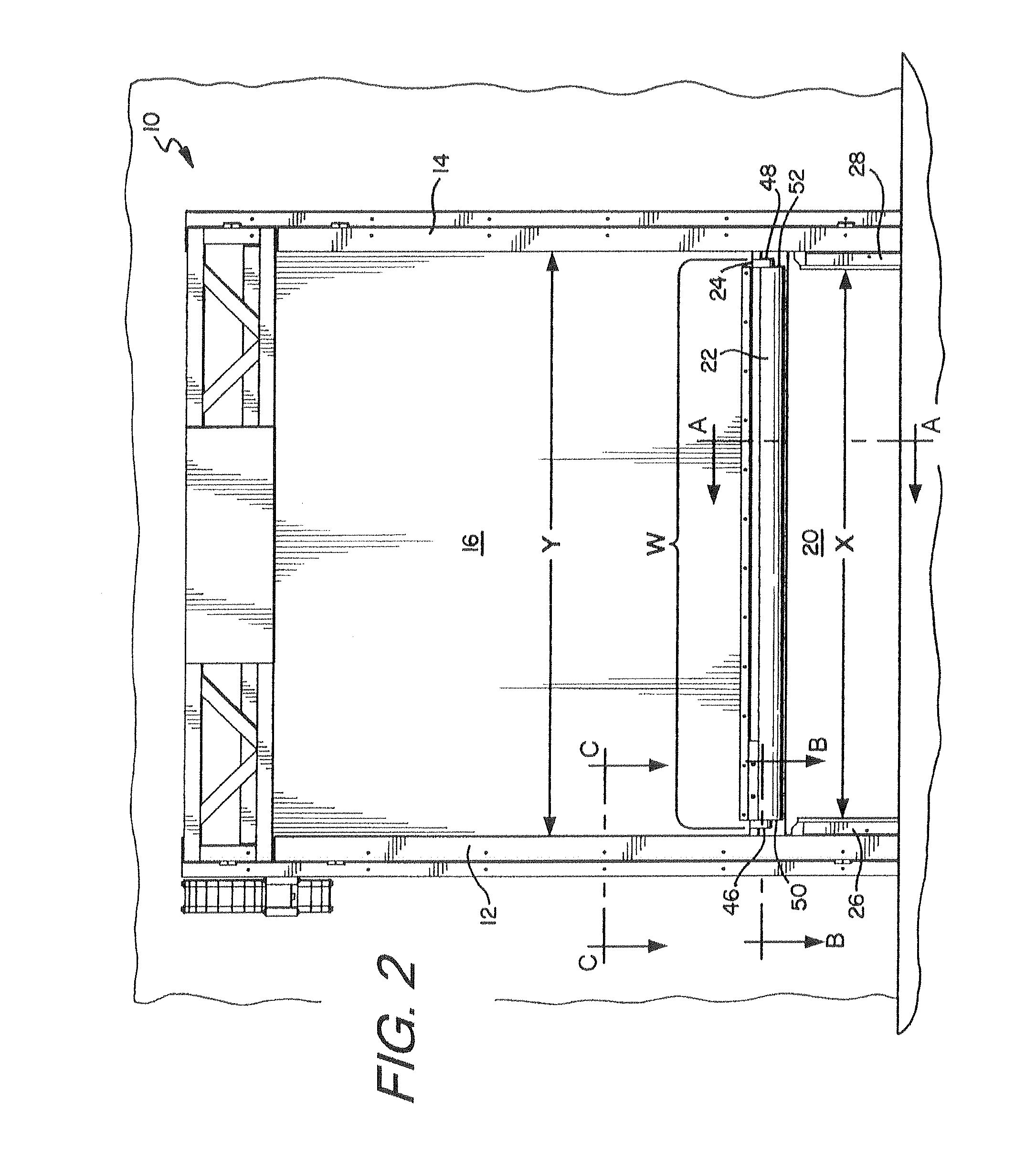
[0037]FIGS. 1, 2, and 6 show a door assembly 10 in a substantially open position, partially closed position, and substantially closed position, respectively. Door assembly 10 includes side columns 12, 14, flexible door panel 16, drum 18 for winding and unwinding flexible door panel 16 to permit and prohibit access to opening 20, bottom bar 22 attached proximate leading or bottom edge 24 of door panel 16, and bottom bar guides 26, 28 disposed proximate a lower portion of opening 20.

[0038]It is contemplated by the invention that bottom bar 22 may be any bottom bar structur...


PUM

PropertyMeasurementUnit
distanceaaaaaaaaaa
widthaaaaaaaaaa
widthaaaaaaaaaa

Abstract

A door assembly having a flexible door panel wound and unwound on a drum or the like to selectively block or permit access through an opening, the flexible door panel having a stiffness, a width, and a length. The door assembly further includes vertically extending side columns disposed on opposite sides of the opening, the side columns being configured to engage a marginal edge of the flexible panel to vertically guide the panel while opening or closing. Attached to a leading edge of the door panel is a bottom bar having a greater stiffness than the door panel and a narrower width than a distance between the vertical panel guide assemblies. Bottom bar guides are disposed proximate a lower portion of the opening and are configured to engage a portion of the bottom bar only when the bottom bar is located in at least a partially closed position.

Description

RELATED APPLICATIONS[0001]This application claims priority to U.S. Provisional Application Ser. No. 61 / 466,754 entitled “Device and Method for Increasing the Wind Load Resistance and Disengage-ability of Overhead Roll-up Doors” filed Mar. 23, 2011, the contents of which are fully incorporated herein by reference.FIELD OF THE INVENTION[0002]The present invention is related to overhead roll-up doors, and more specifically to a device and method for increasing the wind load resistance of the door while enhancing the ability of the door and its components to disengage from a guided path if the door and / or its components are impacted by an object imparting a transverse force when the door is opening or closing.BACKGROUND OF THE INVENTION[0003]Overhead roll-up doors provide resistance to high winds or wind loads and / or air pressure applied to a door panel when in a partially or fully closed position. These doors are typically guided up and down in side columns or vertical guide assemblies...

Claims


Application Information

Patent Timeline
Patent Type & Authority Patents(United States)
IPC IPC(8): E06B9/17
CPCE06B9/13E06B9/58E06B9/581E06B9/17046Y10T29/49826E06B2009/6836E06B2009/585
Inventor DRIFKA, BRIAN NORBERT
Owner RYTEC CORP
Why Eureka
Try Eureka