Unlock instant, AI-driven research and patent intelligence for your innovation.

Image processing apparatus and image processing method

a technology of image processing apparatus and image processing method, which is applied in the direction of visual presentation, instruments, digital computers, etc., to achieve the effect of reducing notches in edge portions

Active Publication Date: 2013-12-31
CANON KK
View PDF12 Cites 4 Cited by
  • Summary
  • Abstract
  • Description
  • Claims
  • Application Information

AI Technical Summary

Benefits of technology

The present invention is an image processing apparatus that reduces notches in edge portions of images by determining whether or not to perform smoothing processing according to the density difference of image data. This avoids the problem that smoothing processing may add correction data to the boundary between objects of the same color and different attributes. Additionally, the determination signal is corrected according to attribute data to prevent unnecessary smoothing processing on objects that do not require it. Overall, this invention improves image quality and provides more accurate and precise image processing.

Problems solved by technology

The above-described technique, however, poses the problem of adverse effects caused by the use of attribute data at the time of determining whether or not to perform smoothing processing on an edge portion, the attribute data representing the attributes of objects included in image data, such as characters, lines, figures, and images.
Referring to the attribute data in FIG. 10B, “I” represents the attribute of an image and “G” represents the attribute of a graphic, and it can be seen from FIG. 17 that there is a problem in that smoothing processing adds correction data to the boundary between the image and the graphic.

Method used


Image

  • Image processing apparatus and image processing method
  • Image processing apparatus and image processing method
  • Image processing apparatus and image processing method

Examples


example configuration

and Image Processing According to Embodiment of Present Invention

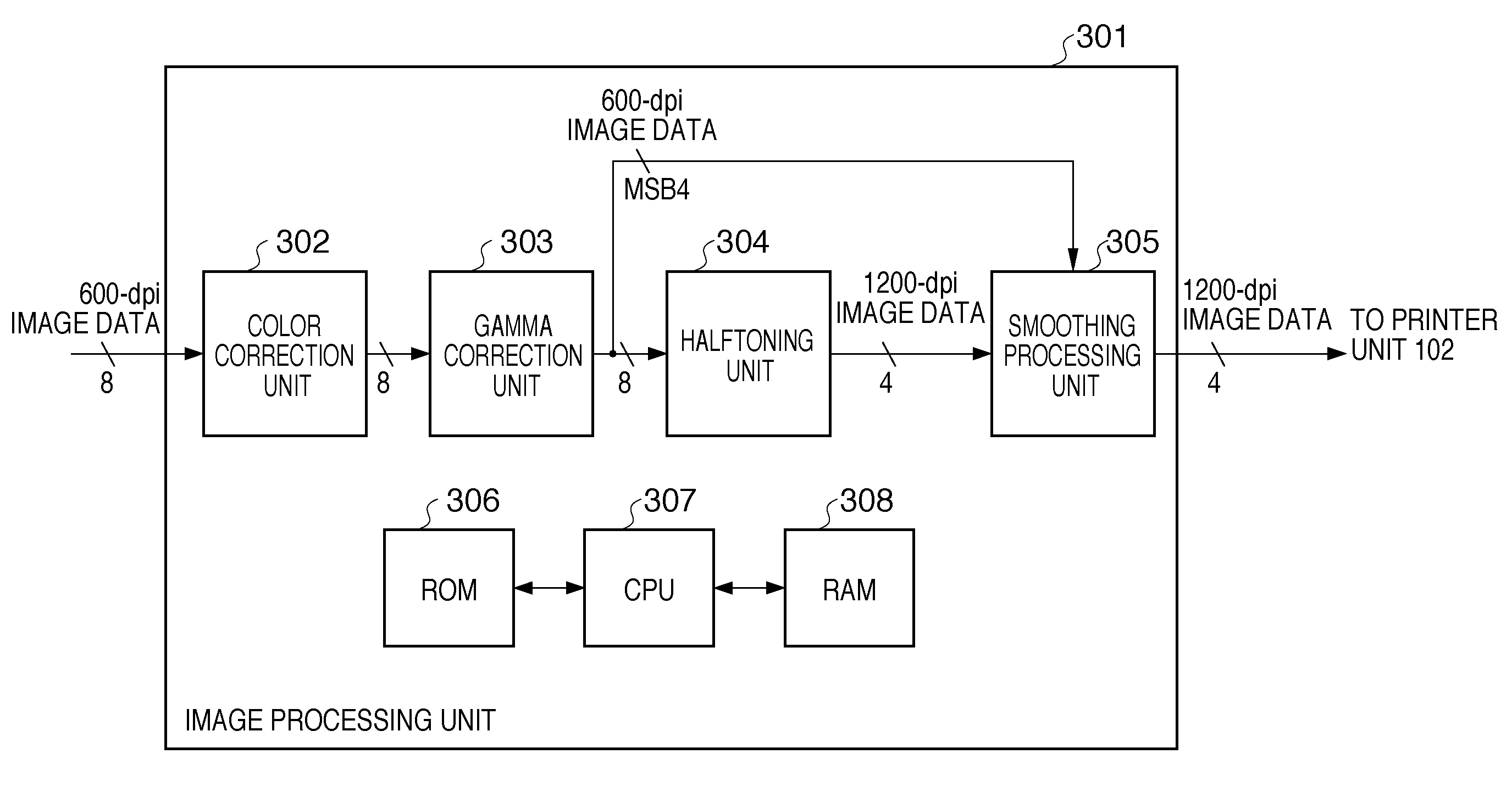
[0051]Next, the abovementioned image processing for printing will be described in detail with reference to FIG. 3A.

[0052]In FIG. 3A, the reference numeral 301 denotes an image processing unit that performs image processing for printing in the controller 102. Referring to the image data and the attribute data that have been input from the memory 105, the image data is subjected to color correction processing by a color correction unit 302 and then converted by a color conversion LUT or matrix computation into a CMYK color space having a density constituted by four image signals. The converted image data hold an 8-bit pixel value for each image signal. Then, through gamma correction processing by a gamma correction unit 303 and digital halftoning through dithering or an error diffusion process by a halftoning unit 304, the image data is converted from an 8-bit pixel value to a 4-bit pixel value that is printable by the p...

specific example 1

[0080]In the case where a reference area 601 illustrated in FIG. 7A is input into the smoothing determination unit 402, the pixel value “15” of pixels 602 is obtained as a maximum value in step S501 and the pixel value “0” of pixels 603 is obtained as a minimum value in step S502. Then, in step S503, the density difference therebetween, “15”, is compared with the threshold value Zsub. In the present embodiment, the threshold value Zsub is assumed to be “4”, so that the density difference in the reference area 601 is higher than the threshold value Zsub, and accordingly, the value of “1” is output into the edge correction unit 406 as the determination signal OutDataZ for the reference area 601.

[0081]The reference area 601 is also input into the edge correction data generation unit 403, so that an average value AVE of “7” is obtained in step S901 and a binarized reference area 1201 illustrated in FIG. 7B is obtained in step S902. Here, in the present embodiment, the threshold value th...

specific example 2

[0083]Similarly, in the case where a reference area 701 illustrated in FIG. 8A is input into the smoothing determination unit 402, a maximum value is the pixel value “7” of pixels 702 and a minimum value is the pixel value “0” of pixels 703. Thus, the density difference “7” therebetween and the threshold value Zsub are compared, so that the determination signal OutDataZ is set to “1”. Meanwhile, the edge correction data generation unit 403 obtains an average value AVE of “4”, and since all of the pixels in the reference area 701 are lower than the threshold value threSST, they are binarized into “0” so that a reference area 1301 illustrated in FIG. 8B is obtained. Then, since the binarized reference area 1301 illustrated in FIG. 8B does not match any of the edge patterns in FIGS. 5A and 5B, the value of “4” is output as the edge correction data in step S908.

[0084]The edge correction unit 406 inputs, in addition to the above-described determination signal and the above-described edge...


PUM


Abstract

For reducing jaggies in second image data based on first image data, the second image data obtained by performing digital halftoning on each image signal of the first image data, and attribute data indicating the attribute of each pixel in the first image data, a determination signal indicating whether or not to perform smoothing processing is output based on the first image data, edge correction data for the smoothing processing is generated from the first image data, and whether or not to perform edge correction processing that uses the edge correction data is selected according to the determination signal and the attribute data. Moreover, the second image data and the edge correction data are compared for each image signal so as to output either one thereof according to the comparison result.

Description

BACKGROUND OF THE INVENTION[0001]1. Field of the Invention[0002]The present invention relates to an image processing apparatus and an image processing method that reduce jaggies in edge portions of image data performed digital halftoning.[0003]2. Description of the Related Art[0004]Conventionally, some techniques have been proposed for reducing notches called jaggies that occur in edge portions of characters or the like in an image processing apparatus. There are various reasons why jaggies can occur, based on the type of jaggies. Jaggies can be roughly divided into two kinds, stairs of pixels caused by a low-resolution printer and notches caused by digital halftoning such as screen processing.[0005]For reducing the former stairs of pixels, there is, for example, a technique to match patterns on binary images so as to detect edges and to thereby add a pixel that corresponds to a pattern to a matched location or remove a pixel (see Japanese Patent Laid-Open No. 10-42141, for example)...

Claims


Application Information

Patent Timeline
Patent Type & Authority Patents(United States)
IPC IPC(8): H04N1/405
CPCH04N1/4092H04N1/405
Inventor KASHIBUCHI, YOICHIKABURAGI, HIROSHI
Owner CANON KK