Sealing wellhead members with bi-metallic annular seal

a sealing and annular seal technology, applied in the direction of sealing/packing, mechanical equipment, borehole/well accessories, etc., can solve the problem of low yield metal localization and fill defects on the surface of wellhead members, and achieve the effect of improving sealing in wellhead members

Active Publication Date: 2014-01-07
VETCO GRAY
View PDF19 Cites 12 Cited by
  • Summary
  • Abstract
  • Description
  • Claims
  • Application Information

AI Technical Summary

Benefits of technology

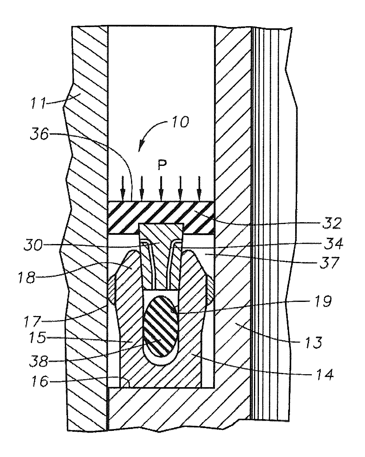
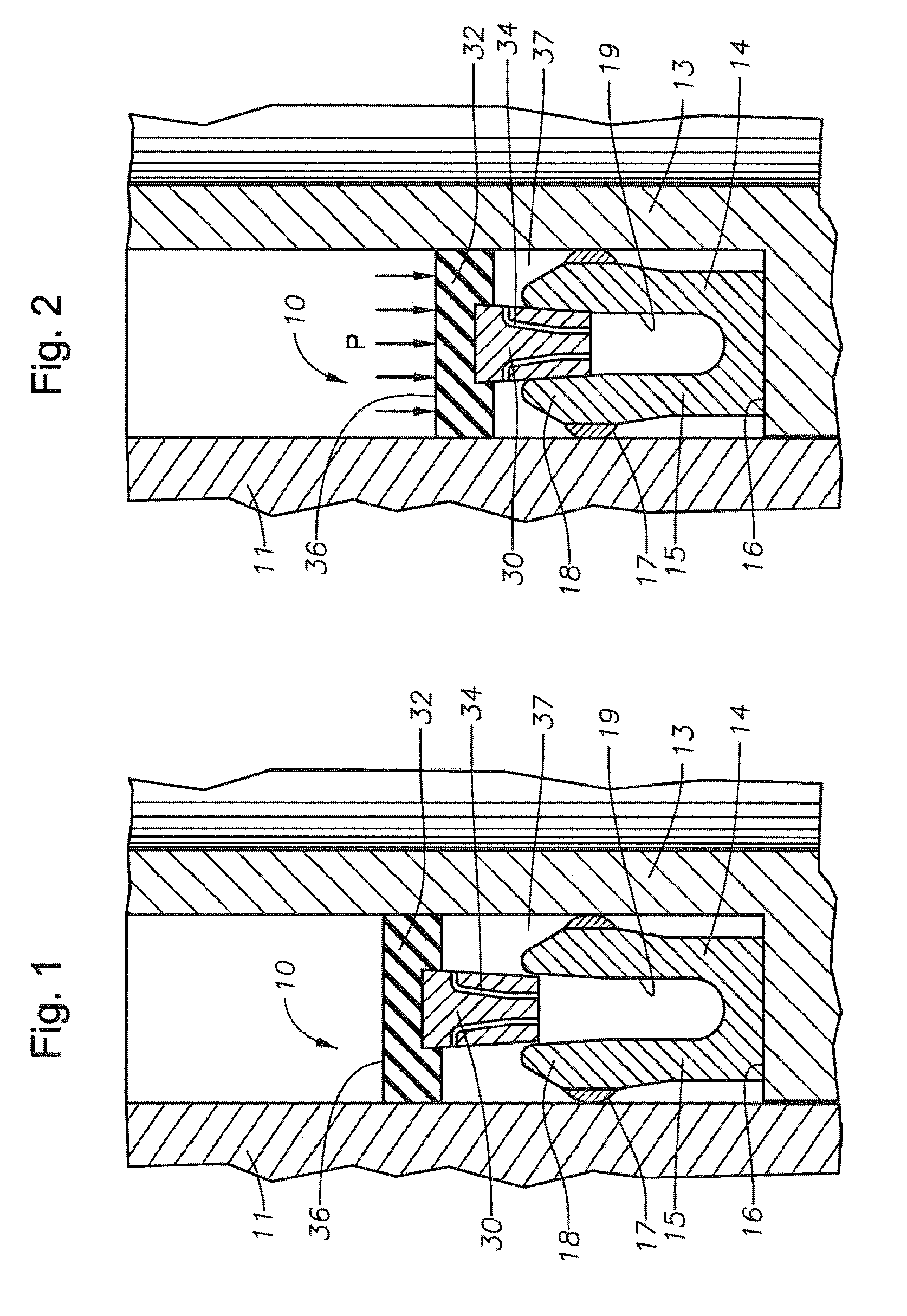
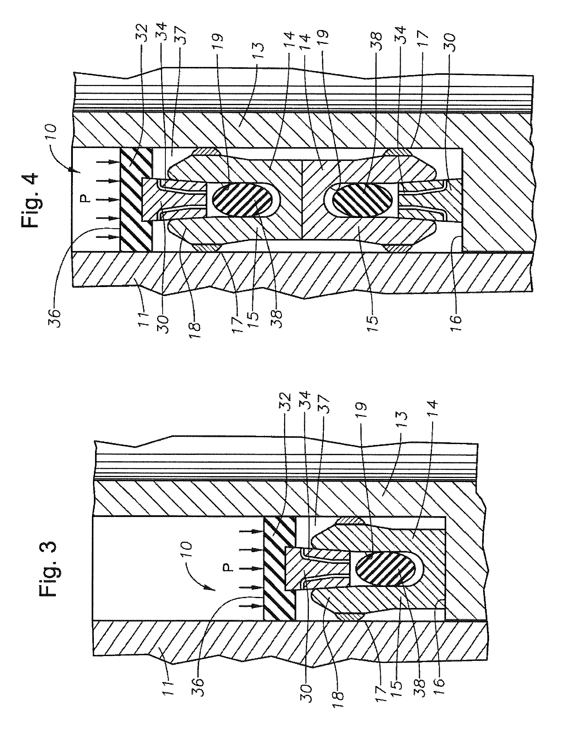
[0006]In an embodiment of the present technique, a bi-metallic seal assembly for use in subsea oil and gas applications is provided that comprises a metallic U-shaped seal that forms a metal-to-metal seal and has features that increase the reliability of the seal assembly in the event surface degradation or defects in a bore of a wellhead member increases the difficulty of maintaining a seal. The seal assembly also has a softer, lower yield metal at regions on the seal assembly where sealing occurs. The U-shaped seal incorporates tapered faces on its internal slot or pocket and is set (conditioned to seal at low pressure) by a test pressure applied to the seal assembly via an interim or bulk seal coupled to a wedge element that drives the legs of the U-shaped seal apart. The softer, low yield metal on the outer portions of the legs is forced against the surfaces of the wellhead members, causing localized yielding of the low yield metal to fill defects on wellhead member surfaces.
[0007]The bulk seal is on the primary pressure side and the taper of the legs is acute enough to prevent friction lock to allow seal retrieval. The wedge may be vented to allow fluid to flow as the wedge is forced into the seal pocket and thus avoid hydraulic lock. An additional compressible element may be fitted into the pocket of the U-shaped seal to avoid hydraulic lock. The compressible element could either be in the pocket or in the annulus formed between the interim seal and the metal seal. Axial loads required to push the seal assembly into its annular space between the wellhead members are minimal as only a small amount of radial squeeze, i.e. interference fit, is needed to maintain a sealing contact at low pressure. This also ensures that if the wedging mechanism fails, a seal can be obtained at least on surfaces without defects. Further, two U-shaped seals may be mounted back to back to allow sealing in two directions.
[0010]The seal assembly can rest on a shoulder formed on the wellhead housing and can be set by pressurizing the annular space between the outer and inner wellhead members to push the seal assembly into place. The combination of the lower yield metal on the exterior of the seal legs, as well as the bulk seal coupled to the wedge, improves sealing in wellhead members having surface degradations.

Problems solved by technology

The softer, low yield metal on the outer portions of the legs is forced against the surfaces of the wellhead members, causing localized yielding of the low yield metal to fill defects on wellhead member surfaces.

Method used


Image

  • Sealing wellhead members with bi-metallic annular seal
  • Sealing wellhead members with bi-metallic annular seal
  • Sealing wellhead members with bi-metallic annular seal

Examples


Embodiment Construction

[0015]Referring to FIG. 1, an embodiment of the invention shows a seal assembly 10 located between a portion of an inner wellhead member that may comprise an isolation sleeve or a tubing hanger 13 having an outer profile and an outer wellhead member that may comprise a wellhead housing, treehead, or casing hanger 11. The isolation sleeve or tubing hanger 13 has a radially extending shoulder 16. The shoulder 16 supports the seal assembly 10 in this embodiment and provides a reaction point during setting operations. Alternatively, the inner wellhead member 13 could instead be a plug, safety valve, or other device, and outer wellhead member 11 could be a tubing spool or a Christmas tree. The annular seal assembly 10 can be fitted to the isolation sleeve or tubing hanger 13 via interference with their outer profile and is pre-assembled onto the isolation sleeve or tubing hanger 13 prior to installation at the well. The seal assembly 10 and tubing hanger 13 can be run into the bore of th...


PUM


Abstract

A wellhead seal assembly that forms a metal-to-metal seal between inner and outer wellhead members. A bi-metallic U-shaped seal with legs having a low yield metal on the outer portions. During installation of the seal assembly, the legs of the seal are forced outward against the surfaces of the wellhead members, by pressurization of a interim non-metallic seal which forces a wedge into the U-shaped seal, causing localized yielding of the low yield metal to fill defects on wellhead member surfaces.

Description

FIELD OF THE INVENTION[0001]This invention relates in general to wellhead assemblies and in particular to a seal for sealing between inner and outer wellhead members.BACKGROUND OF THE INVENTION[0002]Seals are used between inner and outer wellhead tubular members to contain internal well pressure. The inner wellhead member may be a casing hanger located in a wellhead housing and that supports a string of casing extending into the well. A seal or packoff seals between the casing hanger and the wellhead housing. The casing hanger could also be the outer wellhead member, with an isolation sleeve as the inner wellhead member. Alternatively, the inner wellhead member could be a tubing hanger that supports a string of tubing extending into the well for the flow of production fluid. The tubing hanger lands in an outer wellhead member, which may be a wellhead housing, a Christmas tree, or a tubing head. A packoff or seal seals between the tubing hanger and the outer wellhead member.[0003]A v...

Claims


Application Information

Patent Timeline
Patent Type & Authority Patents(United States)
IPC IPC(8): E21B33/03
CPCE21B33/04E21B2033/005E21B2200/01
Inventor SHAW, MICHAEL
Owner VETCO GRAY
Why Eureka
Try Eureka