Medical guidewire

a technology of medical guidewires and guidewires, applied in the field of medical guidewires, can solve the problems of increased resistance generated at the time of manipulating the medical guidewire, increased resistance between the medical guidewire and the guiding catheter, and increased resistance in the depressed portion of the guidewire, so as to improve durability, reduce resistance, and maintain the effect of resistan

Active Publication Date: 2014-01-07
ASAHI INTECC CO LTD
View PDF25 Cites 16 Cited by
  • Summary
  • Abstract
  • Description
  • Claims
  • Application Information

AI Technical Summary

Benefits of technology

[0008]Further, during an operation by a physician, the medical guidewire and the guiding catheter continuously slide. It has thus been necessary to consider the durability of the medical guidewire which can keep the sliding resistance between the medical guidewire and the guiding catheter reduced as long as possible.
[0011]The present invention has been made in view of such circumstances. A first object of the present invention is to provide a medical guidewire reduced in resistance generated in the case of curving a guiding catheter. Further, a second object of the present invention is to provide a medical guidewire improved in durability that can keep the resistance reduced for a long time. Moreover, a third object of the present invention is to provide a medical guidewire which does not inhibit the flow of blood or bodily fluid at the time of manipulation.

Problems solved by technology

However, there has been a problem with this medical guidewire in that in a curved area of a guiding catheter, the sliding resistance between the medical guidewire and the guiding catheter increases.
There has thus been a problem in that the resistance generated at the time of manipulating the medical guidewire also increases due to this depressed portion.
Furthermore, since the depressed portion of the medical guidewire described in Patent Literature 1 has the corner, there has been a problem in that blood or bodily fluid may be accumulated in this depressed portion.

Method used


Image

  • Medical guidewire
  • Medical guidewire
  • Medical guidewire

Examples


first embodiment

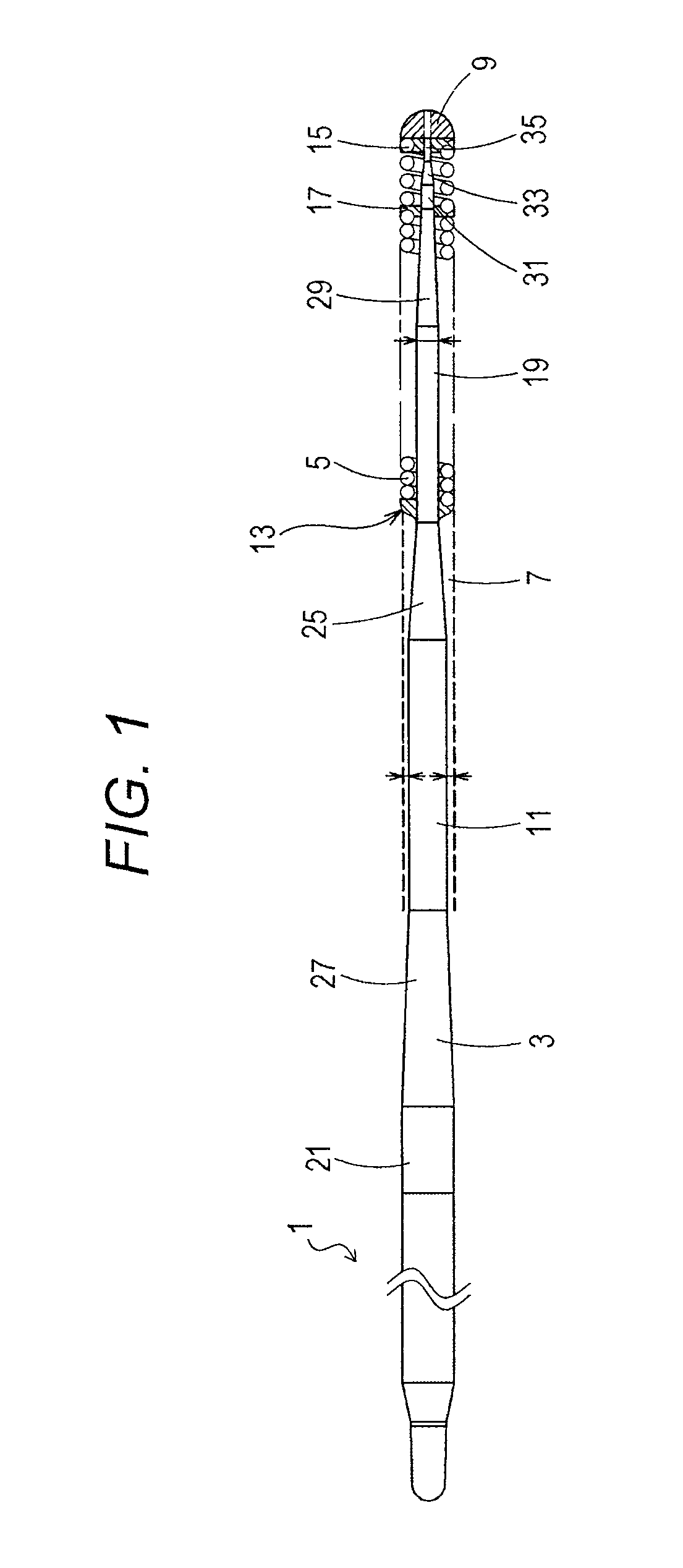
[0036]FIG. 1 illustrates an overall view of a medical guidewire according to a first embodiment of the present invention.

[0037]It is to be noted that in FIG. 1, a description is given with the left side defined as a “proximal end”, and the right side defined as a “tip” for convenience of description.

[0038]Further, in FIG. 1, the medical guidewire is reduced in length direction, and illustrated in an overall schematic manner for the sake of easy understanding. An overall size illustrated in FIG. 1 is thus different from an actual size.

[0039]In FIG. 1, a medical guidewire 1 is made up of a core shaft 3 and a coiled body 5 that covers a tip portion of the core shaft 3. The tip portion of the core shaft 3 and a tip portion of the coiled body 5 are fixed to each other at an extreme tip portion 9.

[0040]A material for the core shaft 3 is not particularly limited. In the present embodiment, stainless steel (SUS304) is used as the material for the core shaft 3. Other than that, a material su...

second embodiment

[0090]Next, a second embodiment of the medical guidewire of the present invention will be described.

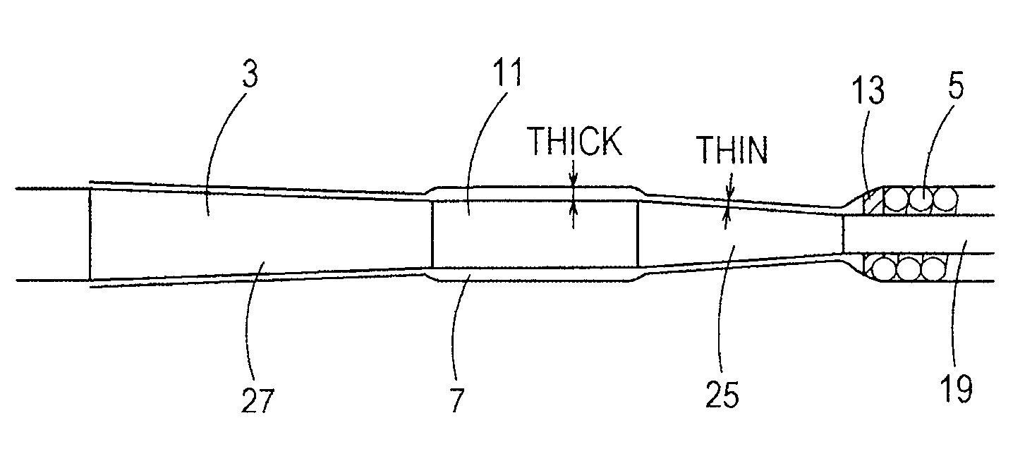
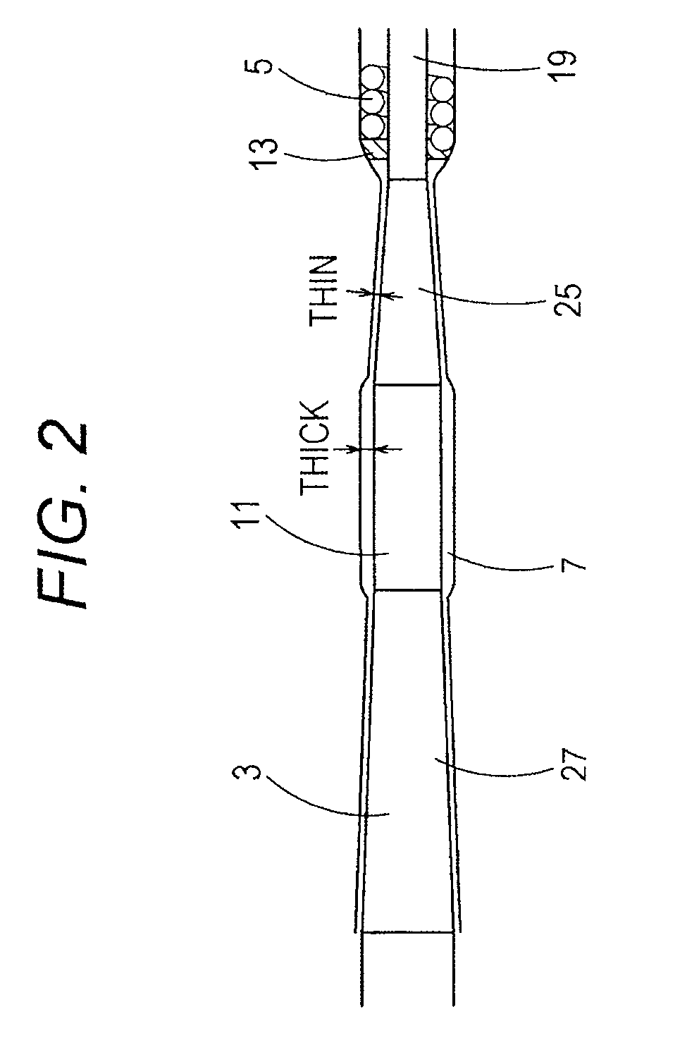
[0091]FIG. 4 illustrates a partially enlarged view of the state of connection between a core shaft and a coiled body in the second embodiment.

[0092]In FIG. 4, the coil-base-end brazed portion 13 is made of a brazing material in streamlined shape which is formed in the area from the proximal end portion of the coiled body 5 to the second taper part 25. The hydrophilic material 7 is applied with a uniform thickness onto the range from the coiled body 5 to the coil-base-end brazed portion 13 and the second taper part 25.

[0093]Also by means of this medical guidewire 1 of the second embodiment, it is possible to reduce the sliding resistance of the medical guidewire 1 at the time of pulling the medical guidewire 1 inside the guiding catheter, the tubular organ or the intracorporeal tissue.

[0094]In the second embodiment, in the area from the proximal end portion of the coiled body 5 to the ...

third embodiment

[0098]Next, a third embodiment of the medical guidewire of the present invention will be described.

[0099]FIG. 5 illustrates a partially enlarged view of the state of connection between a core shaft and a coiled body in the third embodiment.

[0100]In the third embodiment, as illustrated in FIG. 5, the hydrophilic material 7 is applied so as to form a cylindrical shape (or linear shape) in a middle area from the proximal end portion of the coiled body 5 to the second cylindrical part 11. Further, the hydrophilic material 7 is applied so as to form a curved shape in a connecting section between this middle area and the proximal end portion of the coiled body 5, and applied so as to form a curved shape in a connecting section between the middle area and the second cylindrical part. It is thus possible to further reduce the sliding resistance of the medical guidewire 1 at the time of pulling the medical guidewire 1 inside the guiding catheter, the tubular organ or the intracorporeal tissu...


PUM


Abstract

There is provided a medical guidewire which reduces the resistance with a curved guiding catheter, and has improved durability that can keep the resistance reduced for a long time. A core shaft of the medical guidewire has a second cylindrical part, with a smaller diameter than that of a coiled body, on a proximal end side of the coiled body. This second cylindrical part is coated with a hydrophilic material. Further, the hydrophilic material coated on the second cylindrical part has a larger thickness than a hydrophilic material coated on the coiled body.

Description

CROSS REFERENCE TO RELATED APPLICATIONS[0001]This application is based on Japanese Patent Application No. 2010-010576 filed with the Japan Patent Office on Jan. 21, 2010, the entire content of which is hereby incorporated by reference.TECHNICAL FIELD[0002]The present invention relates to a medical guidewire.BACKGROUND ART[0003]There have conventionally been proposed a variety of medical guidewires for guiding a medical equipment such as a catheter which is used by being inserted into tubular organs such as blood vessels, digestive tracts and ureters, and intracorporeal tissues.[0004]For example, a medical guidewire described in Patent Literature 1 (Japanese Patent Application Laid-Open No. 2008-307367) is made up of a wire body, a coil, a resin coating layer coated on this coil, and an annular member. The wire body has a certain diameter in a portion closer to the rear end than a tip portion, which is formed in tapered shape. The coil is a spiral coil that is wound around the tip po...

Claims


Application Information

Patent Timeline
Patent Type & Authority Patents(United States)
IPC IPC(8): A61B5/00
CPCA61M2025/09083A61M25/09A61M2025/09133
Inventor MAKI, HIDEAKIGOTO, SHINICHIKATO, TADAKAZU
Owner ASAHI INTECC CO LTD
Why Eureka
Try Eureka