Sand separator for petroleum and natural gas wells

a technology for petroleum and natural gas wells and separators, which is applied in the direction of separation processes, wellbore/well accessories, liquid displacement, etc., can solve the problems of adjusting surface equipment, affecting the pressure and velocity of return fluid, and sand and debris can wreak havoc on choke valves that reduce the return fluid, etc., to reduce the velocity of the fluid remaining inside the flue

Active Publication Date: 2014-01-07
BOYD KEITH L +2
View PDF18 Cites 26 Cited by
  • Summary
  • Abstract
  • Description
  • Claims
  • Application Information

AI Technical Summary

Benefits of technology

[0008]A sand separator for capturing sand and rock debris from recovered natural gas fracturing fluid includes a cylindrical, high-pressure-rated vessel disposed vertically and immediately downstream of the gas wellhead. High pressure fracturing fluid enters the top of the separator into an inner flue extending coaxially downward to terminate a spaced distance above the bottom of the vessel. Transverse baffles spaced apart along the length of the flue extend through the flue to the inner walls of the vessel to keep the flue centered within the separator. As the fluid enters the separator, openings through the flue near the vessel inlet permit lighter weight and gaseous constitu

Problems solved by technology

Fracturing fluid contains a considerable amount of fracturing sand.
Such sand and debris can wreak havoc upon choke valves that reduce the return fluid pressure and velocity downstream of the wellhead, and upon rel

Method used


Image

  • Sand separator for petroleum and natural gas wells
  • Sand separator for petroleum and natural gas wells
  • Sand separator for petroleum and natural gas wells

Examples


Embodiment Construction

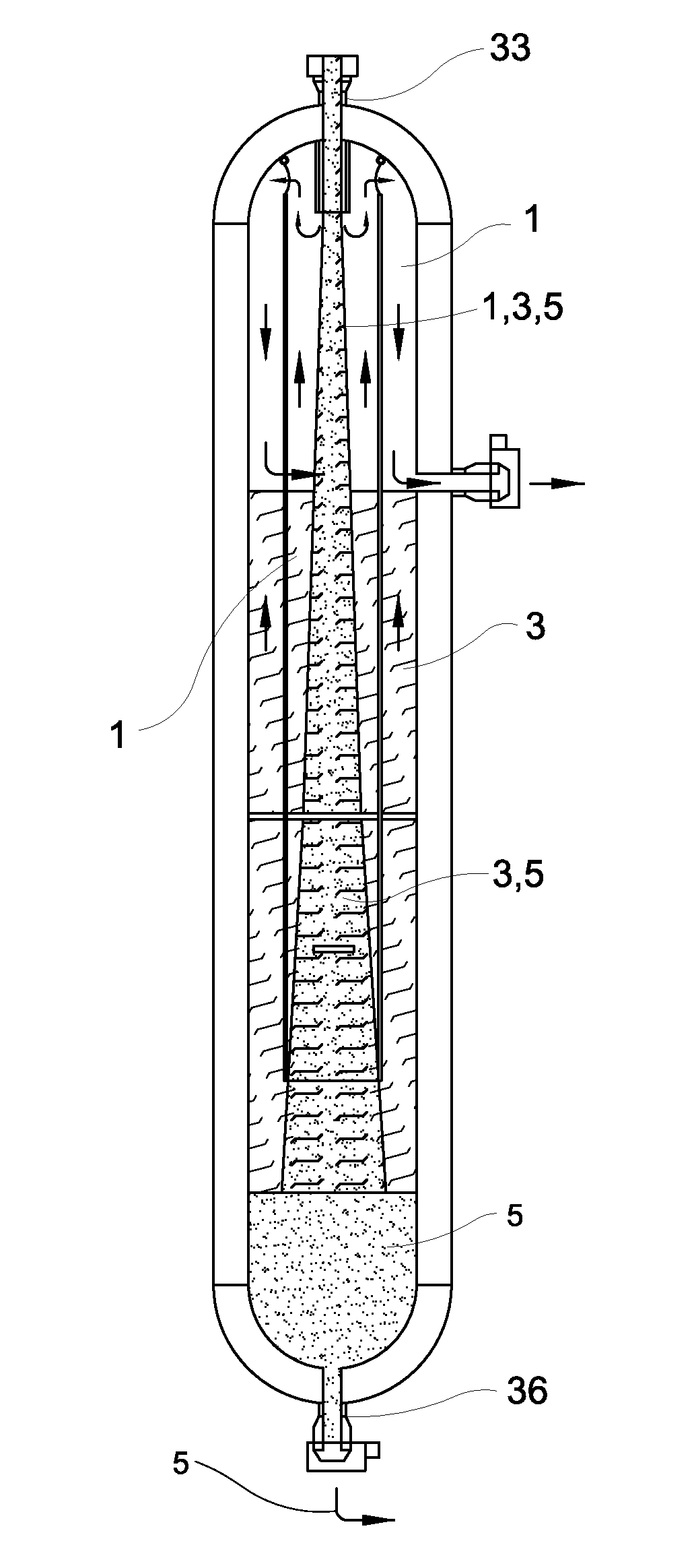
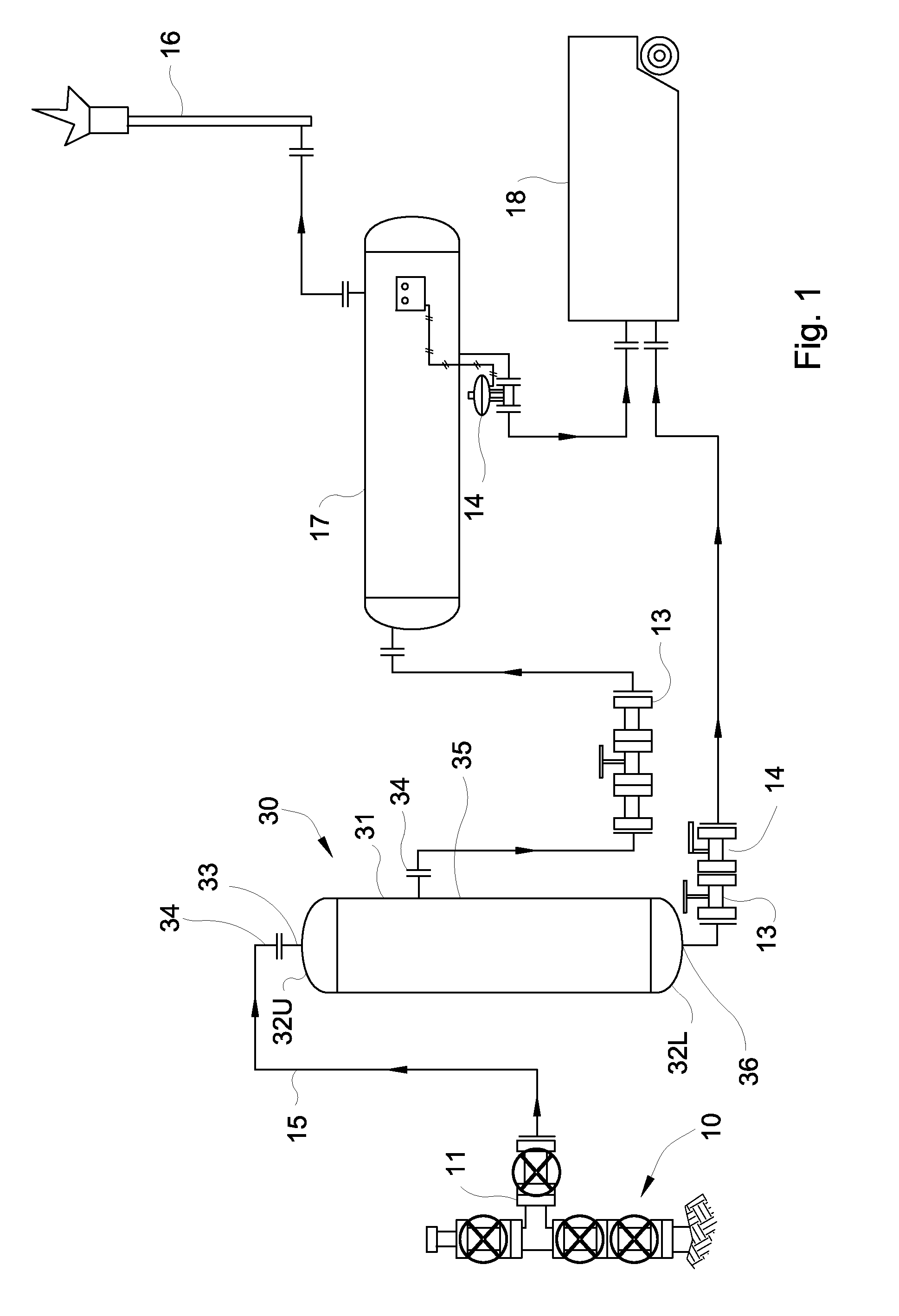
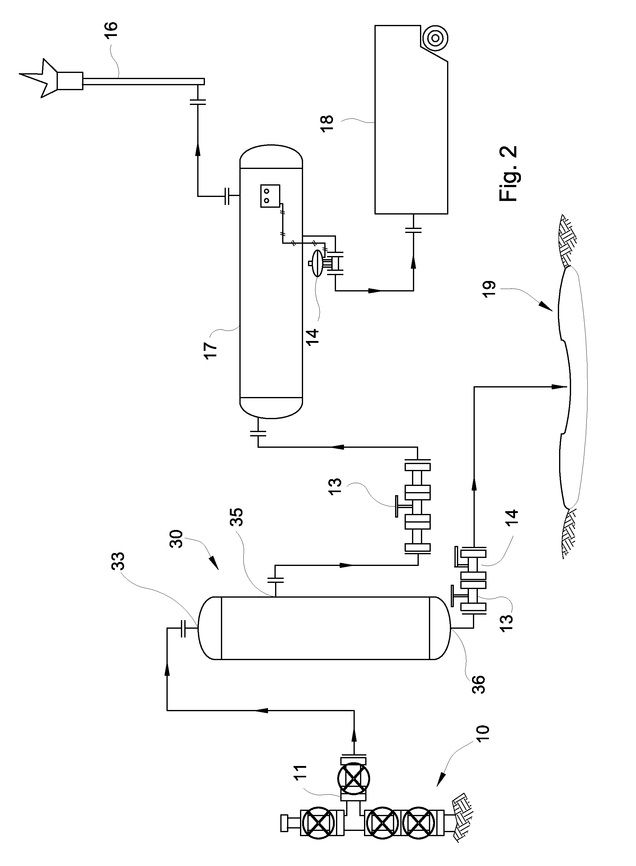
[0015]Referring first to FIGS. 1-3, the present invention comprises sand separator 30 installed at a natural gas well downstream from wellhead 10 and upstream from choke valve manifold 13 and other well site equipment 17, 21, 23. Sand separator 30 traps and separates sand and rock debris 5 within a stream of gaseous 1 and liquid 3 fluids effluent from wellhead 10. See also FIGS. 4A-4C. Under high pressure, gas 1 effectively is dissolved in water 3, and the fluid F leaving wellhead 10 moves under such high pressure and velocity that solids 5 remain substantially uniformly suspended in water 3. The unsurprising effect (absent sand separator 30) is to erode and damage relatively sensitive wellhead equipment, including choke valve manifold 13 adapted to reduce the velocity and pressure of the fluid before entering other equipment 17, 21, 23. NOTE: hereinafter, the term “fluid F” will be used primarily to refer to hydraulic fracturing fluid, which, at various stages, may include varying ...


PUM

PropertyMeasurementUnit
Lengthaaaaaaaaaa
Pressureaaaaaaaaaa
Flow rateaaaaaaaaaa

Abstract

A sand separator for capturing sand and rock debris from recovered natural gas fracturing fluid includes a cylindrical, high-pressure-rated vessel disposed vertically and immediately downstream of the gas wellhead. High pressure fracturing fluid enters the top of the separator into an inner flue extending coaxially downward to terminate a spaced distance above the bottom of the vessel. Transverse baffles spaced apart along the length of the flue extend through the flue to the inner walls of the vessel to keep the flue centered within the separator. As the fluid enters the separator, openings through the flue near the vessel inlet permit lighter weight and gaseous constituents to escape the fluid and bypass the flue, thereby reducing the velocity of the fluid remaining inside the flue. As the remaining fluid falls to the bottom of the vessel, it further slows as it reverses direction to rise between the flue and the vessel walls. At the bottom of the vessel, sand and rock debris precipitates out of the slowed fluid and accumulates above a clean-out valve by which the debris periodically may be removed. The gas and fluid recombine relatively free of sand and rock debris and exit the vessel at one or more outlet ports through the vessel walls. The sand separator functions in both exploration and production wells for both petroleum and natural gas.

Description

[0001]This application claims priority from a Provisional Application Ser. No. 61 / 328,883, filed Apr. 28, 2010.BACKGROUND OF THE INVENTION[0002]1. Field of the Invention[0003]This invention relates generally to petroleum and natural gas and oil wells, and particularly to wellhead site equipment. More particularly, this invention relates to a sand separator installed at the wellhead upstream of other surface equipment for separating sand and rock debris from well effluent fluids.[0004]2. Description of Related Art[0005]Exploration for methane, or natural gas, involves injection of high-pressure fluids (mostly water with sand) directly into underground rock formations expected to yield natural gas, a process commonly referred to as “hydraulic fracturing.” The water pressure fractures the rock strata, whereupon entrapped natural gas escapes into the well bore to be captured at the surface and piped to market. Hydraulic fracturing fluid is recovered from the exploration wells and dispos...

Claims


Application Information

Patent Timeline
IPC IPC(8): E21B43/34B01D21/24B01D19/00
CPCE21B43/34B01D19/0042B01D21/2405B01D2221/08B01D2221/04B01D21/2494E21B43/35
Inventor BOYD, KEITH L.WHITSETT, SCOTTY L.KINDER, KEVIN J.
Owner BOYD KEITH L
Why Eureka
Try Eureka