Process and plant for producing methanol

a technology of methanol and synthesis gas, which is applied in the direction of organic compound preparation, liquid gas reaction process, and compound preparation, etc., can solve the problems of difficult design of the reactor, limited co content of usable synthesis gas, and condensation of methanol product, so as to avoid condensation of methanol. , the effect of avoiding condensation

Active Publication Date: 2014-01-14
LURGI
View PDF6 Cites 10 Cited by
  • Summary
  • Abstract
  • Description
  • Claims
  • Application Information

AI Technical Summary

Benefits of technology

[0005]It is the object of the invention to reliably avoid the condensation of methanol at the outlet of the gas-cooled second reactor in particular when using a water-cooled first reactor.
[0006]This object substantially is solved with the invention in that the cooling gas flows through the second reactor cocurrent to the mixture withdrawn from the first reactor. The distance of the product temperature from the dew point at the lower end of the reactor thereby is increased, so that a methanol condensation largely is excluded. By avoiding a two-phase flow, an improved reactor control can also be achieved. At the same time, pressure losses and / or fluctuations of the reactor pressure can reliably be avoided.
[0007]Since the use of a water-cooled first reactor provides for using a “sharper” synthesis gas with higher CO contents than in an adiabatic reactor according to U.S. Pat. No. 7,144,923 B2, the conversions can be increased and a higher concentration of methanol and water as coupling product in the product gas can be achieved after the first reactor. This leads to a higher dew point, so that avoiding condensation in the second reactor becomes even more important.
[0008]In accordance with a preferred aspect of the process it is provided that as cooling gas for the second reactor synthesis gas is used, which has been separated from the mixture withdrawn from the second reactor. In this way, a maximum utilization of the heat obtained by the exothermal reaction process can be achieved.

Problems solved by technology

In the case of unsteady plant conditions and in particular in the case of an improper start-up of the reactor by too early addition of fresh synthesis gas, this procedure can, however, lead to a condensation of the methanol product in the gas-cooled second reactor, since the reactor wall temperature at the outlet can approach the dew point of the product gas.
When using an adiabatic first reactor, however, the CO content of the usable synthesis gas is restricted, since the control of the exotherm in the first reactor can create problems.
In addition, it is required to perform cooling of the partly converted synthesis gas after each stage of the first reactor, which complicates the design of the reactor.

Method used


Image

  • Process and plant for producing methanol
  • Process and plant for producing methanol
  • Process and plant for producing methanol

Examples


Embodiment Construction

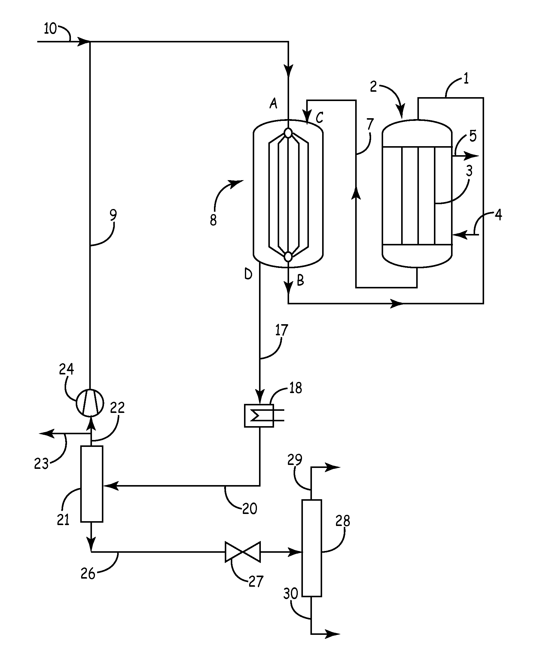
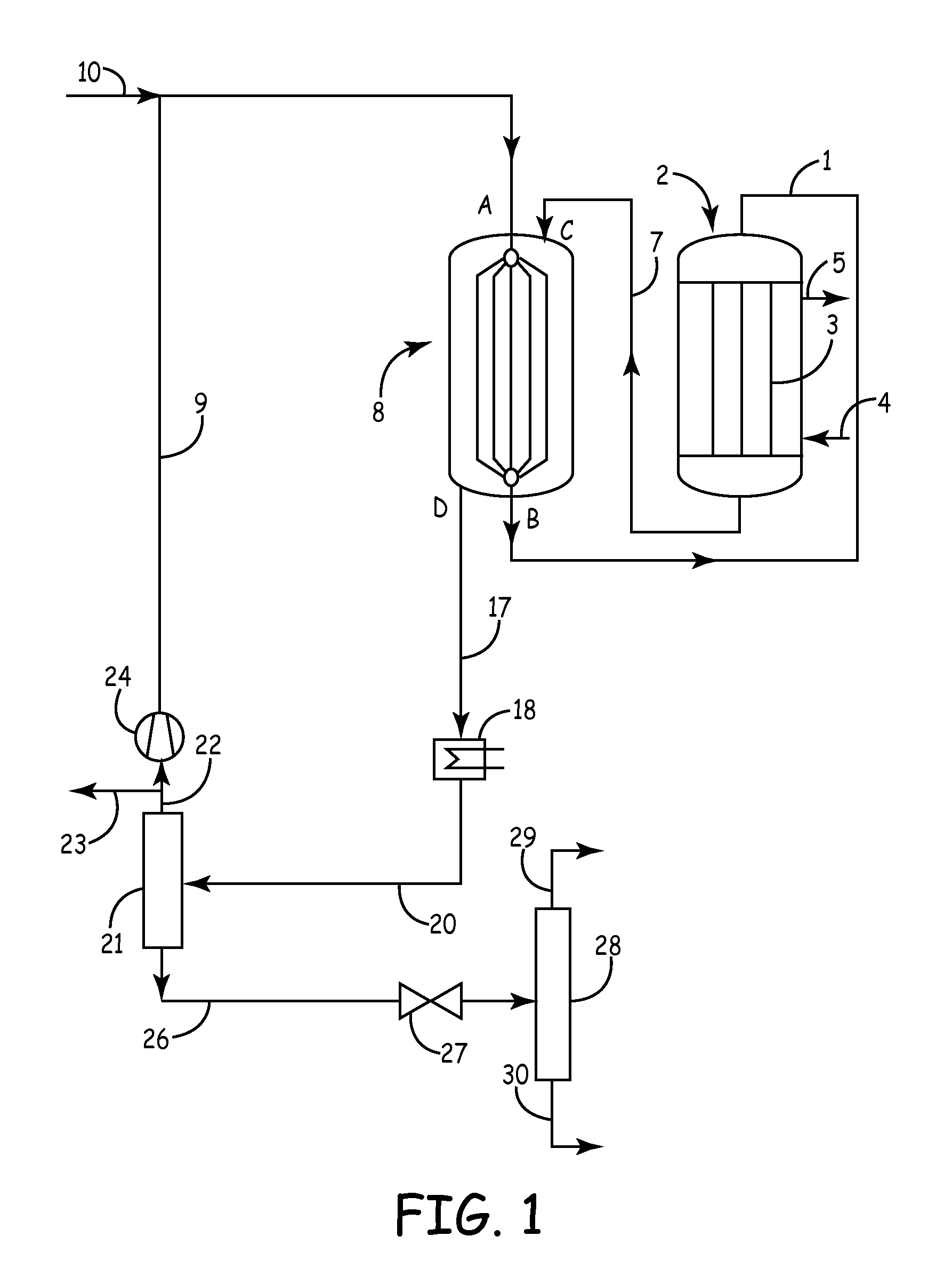
[0018]In the plant shown in FIG. 1, a mixture of fresh and recirculated synthesis gas is passed through a conduit 1 into a first synthesis reactor 2. This first reactor 2 for example is a tubular reactor known per se, in which for example a copper catalyst is arranged in tubes 3. As coolant, water boiling under elevated pressure is used, which is supplied in conduit 4. A mixture of boiling water and steam is withdrawn in conduit 5 and supplied to a non-illustrated steam drum known per se for energy recovery.

[0019]The synthesis gas entering the first reactor 2 is preheated to a temperature>220° C., since the catalyst will only respond from this temperature. Usually, the gas temperature at the inlet of the first reactor 2 is about 220 to 280° C. and the pressure lies in the range from 2 to 12 MPa (20 to 120 bar), preferably in the range from 4 to 10 MPa (40 to 100 bar). The coolant which is withdrawn via conduit 5 usually has a temperature in the range from 240 to 280° C. Depending on...


PUM

PropertyMeasurementUnit
temperatureaaaaaaaaaa

Abstract

For producing methanol from a synthesis gas containing hydrogen and carbon oxides the synthesis gas is passed through a first, water-cooled reactor in which a part of the carbon oxides is catalytically converted to methanol. The resulting mixture containing synthesis gas and methanol vapor is supplied to a second, gas-cooled reactor in which a further part of the carbon oxides is converted to methanol. Subsequently, methanol is separated from the synthesis gas, and synthesis gas is recirculated to the first reactor. The cooling gas flows through the second reactor cocurrent to the mixture withdrawn from the first reactor.

Description

CROSS-REFERENCE TO RELATED APPLICATIONS[0001]This application is a national stage application under 35 U.S.C. 371 of International Patent Application Serial No. PCT / EP2009 / 005483, entitled “Process and Plant for Producing Methanol,” filed Jul. 29, 2009, which claims priority from German Patent Application No. 10 2008 049 621.9, filed Sep. 30, 2008.FIELD OF THE INVENTION[0002]This invention relates to the production of methanol from a synthesis gas containing hydrogen and carbon oxides, wherein the synthesis gas is passed through a first, water-cooled reactor in which a part of the carbon oxides is catalytically converted to methanol, wherein the resulting mixture containing synthesis gas and methanol vapor is supplied to a second, gas-cooled reactor in which a further part of the carbon oxides is catalytically converted to methanol, wherein methanol is separated from the synthesis gas and wherein synthesis gas is recirculated to the first reactor.BACKGROUND OF THE INVENTION[0003]Pro...

Claims


Application Information

Patent Timeline
Patent Type & Authority Patents(United States)
IPC IPC(8): C07C27/00
CPCB01J8/067B01J2219/0004C07C29/152B01J2208/00274C07C31/04
Inventor KOPETSCH, HANSHACKEL, PHILIPP MARIUSGRONEMANN, VERONIKAMORGENROTH, RAINER
Owner LURGI
Why Eureka
Try Eureka