Magnetic flux power generation based on oscilating movement

a technology of magnetic flux and power generation, applied in the direction of dynamo-electric components, dynamo-electric machines, electrical apparatus, etc., can solve the problems of reducing dimensions, reducing the support stability of pivoting points, and requiring recharge, so as to prevent lateral rotation, improve the stability of pivoting points, and minimize energy

Inactive Publication Date: 2014-01-21
UNIV DE BARCELONA +1
View PDF10 Cites 5 Cited by
  • Summary
  • Abstract
  • Description
  • Claims
  • Application Information

AI Technical Summary

Benefits of technology

[0012]This design presents as advantages its extreme simplicity and low price, since the elements that constitute it are obtained employing well-established technologies and the materials have a low acquisition cost. Thus, it is possible to integrate the proposed device in constructive elements, such as of a boat, enabling to use the mechanical energy in the environment without that representing a significant use of space.
[0016]The tube's length must be designed according to the expected frequency of oscillation in order to avoid the oscillation to change direction before the magnet has passed from one end of the tube to the other, thus maximizing the energy obtained during each oscillation. More specifically, the higher the frequency the lesser the length of the tube and vice versa. As for the transversal section, it must be adequate for the magnet to rotate inside of it around its axis of revolution. It is further understood that the lesser the space between magnet and the tube, the greater the energy that is generated, always avoiding frictions that cause the magnet to lose mechanical energy.
[0017]In a particular embodiment of the invention, the magnet further comprises pivoting points protruding laterally on its surface through points belonging to its axis of revolution. Meanwhile, the tube comprises opposing longitudinal rails designed to accommodate the magnet's pivoting points. Thus, when a tilting of the tube is produced, the magnet rolls supported on these pivoting points. This way, a minimization of friction of the magnet over the tube is attained, as well as increasing the magnet's rotation speed, since the pivoting points are small in size, a higher rotation speed may be attained at the expense of a lower linear speed, and therefore a higher induced tension. In addition, the pivoting points force the rotation of the magnet in a certain direction, thus guaranteeing optimal magnetization relative to the prism's coil. In order to prevent sliding of the axis as far as possible, the pivoting points will have radial projections that fit into notches made on the rails.
[0020]A preferred embodiment of the invention is directed towards a spherical magnet that travels on the interior of a tube with a circular section. In this case, the poles would have a semi-spherical, quarter-spherical shape, etc., depending on their number. Another preferred embodiment describes a cylindrical magnet traveling along the interior of a tube with a parallelepiped section, in which case the poles will have the shape of a cylindrical sector. It is understood that other forms of the device would be possible, as long as the magnet was obtained as a solid of revolution and the tube had the corresponding complementary shape, and that could help to adjust the design to other particular scenarios. For example, a device with a magnet in the shape of an ellipse of revolution and a tube with an elliptical section could help to improve the support stability of the pivoting points on the tube's rails.
[0021]In a more preferred embodiment of the object of the invention, the magnet travels in the interior of the tube sliding, to that end the magnet is assembled over a ring specially designed to prevent lateral rotation; this way the magnet is prevented from spontaneously adopting an orientation tending to minimize its energy, consequently leading to a nil position of varying magnetic flow.

Problems solved by technology

Power to this kind of systems is normally provided from batteries, which present limitations associated with the need of recharge as well as cost.
In addition, the batteries contain highly polluting elements and require recharge.
Batteries also determine in many cases the final volume of the systems, constituting a limitation to the procurement of systems of increasingly reduced dimensions and which must be autonomous in operation.

Method used


Image

  • Magnetic flux power generation based on oscilating movement
  • Magnetic flux power generation based on oscilating movement
  • Magnetic flux power generation based on oscilating movement

Examples


first embodiment

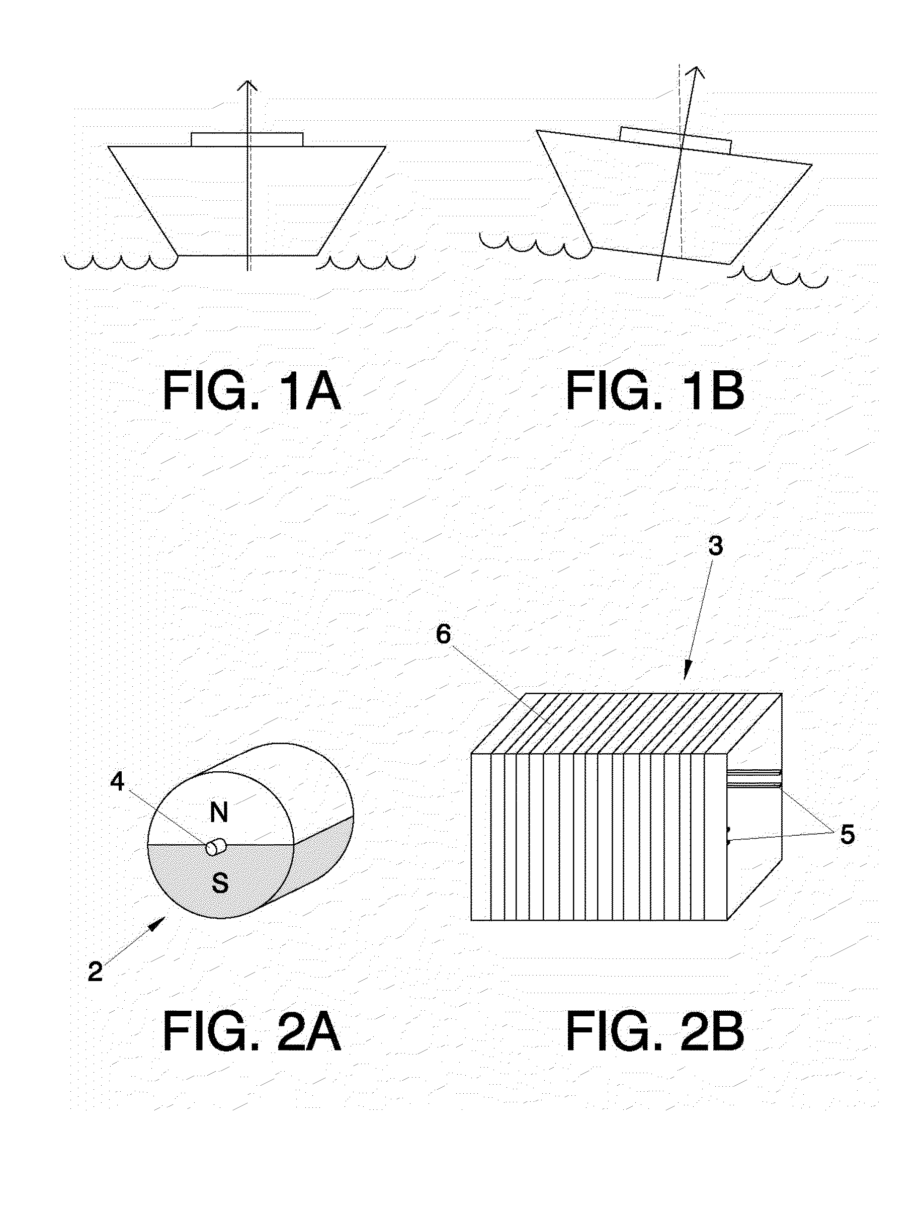
[0029]The first embodiment is represented on FIGS. 2a, 2b and 2c. FIG. 2a shows a cylindrical magnet (2), which in this example comprises only a couple of poles (N, S), and which may rotate around pivoting points (4) which coincide with the ends of the axis of revolution of the cylindrical magnet (2). FIG. 2b, on the other hand, represents the corresponding tube with a parallelepiped section (3), being able to appreciate the rails (5) placed in lines longitudinal to the center of opposing sides, as well as the exterior transversal winding (6). The magnet's (2) contour should be adjusted as much as possible within the tube of parallelepiped section (3), since that way the flow variation induced during its rotation will be maximized, although always avoiding the creation of friction that could slow that rotation movement.

second embodiment

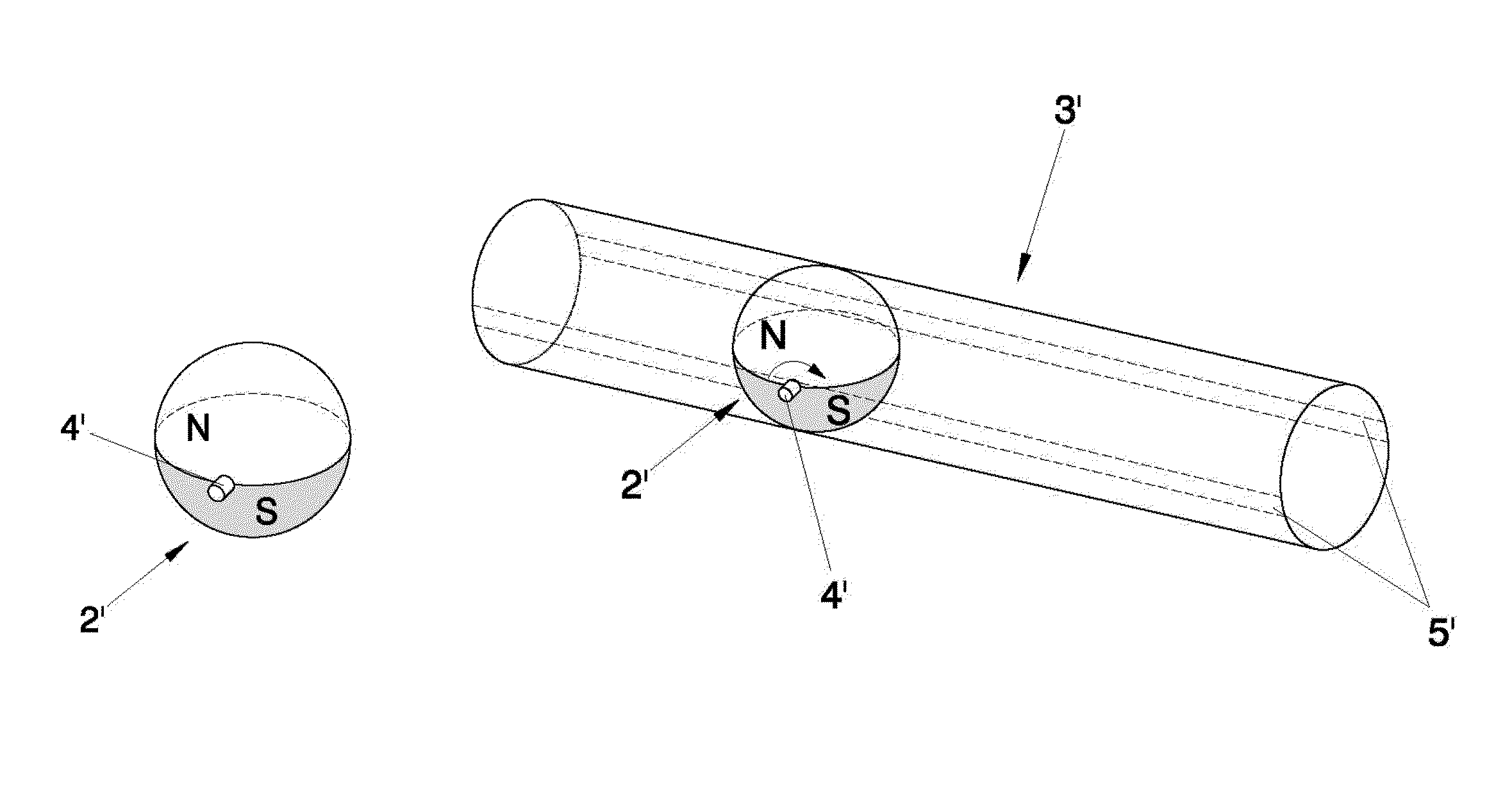
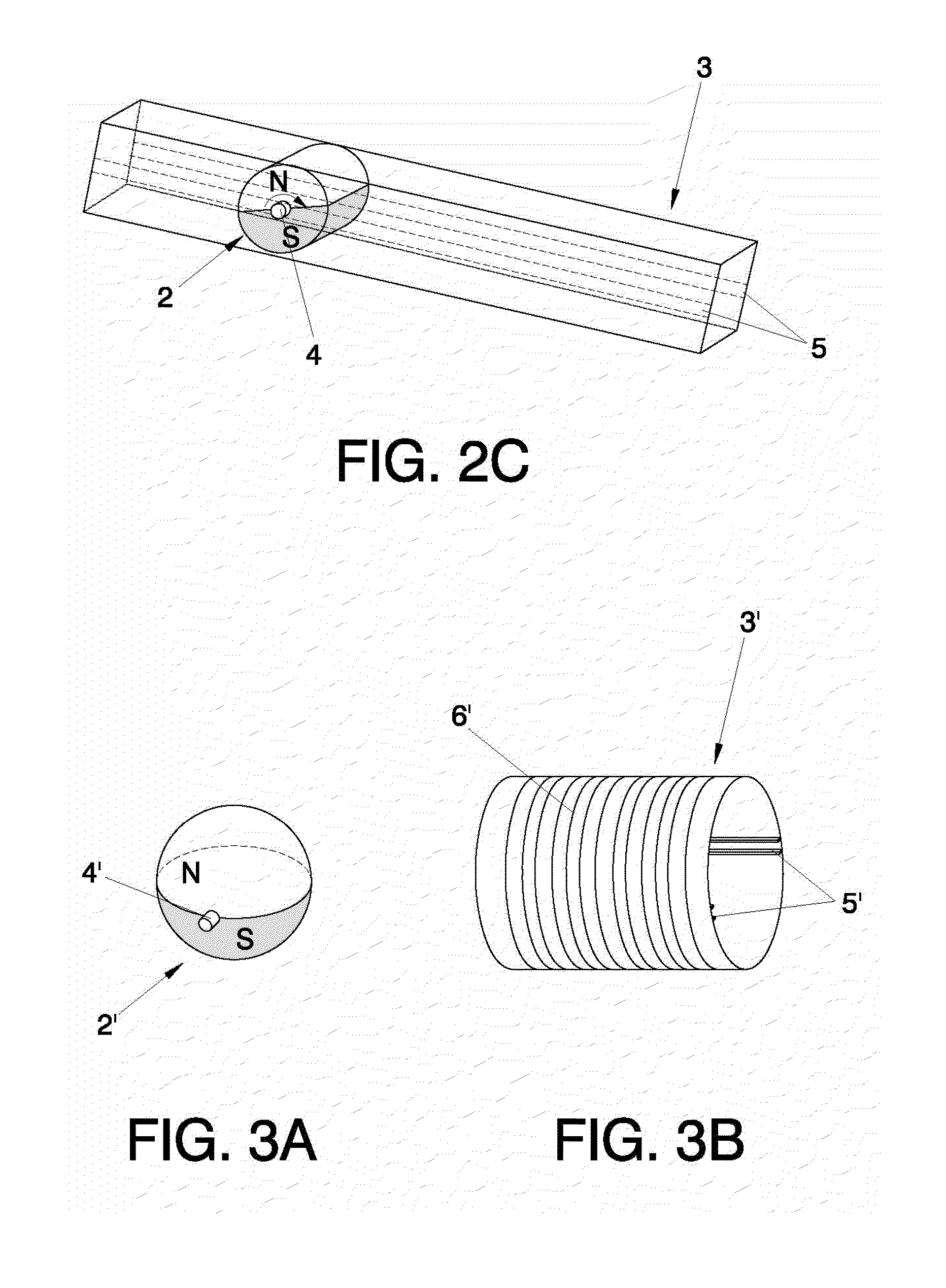
[0030]FIG. 2c shows the device (1) already assembled and in operation during the boat's oscillation. It shows how the parallelepiped shape tube (3) has tilted to the right, and the cylindrical magnet (2) rotates in its interior with the pivoting points (4) supported over the rails (5). Due to clarity of the drawing, the winding (6) has not been represented in this figure. It shows how the rotation of the cylindrical magnet (2) causes the alternative passage of the north (N) and south (S) poles in front of each turn of the winding (6), generating an electromotive force induced at the ends of the winding (6). Described below is the device (1′) of the second embodiment, making reference to FIGS. 3a, 3b, and 3c, where FIGS. 3a and 3b show respectively the spherical magnet (2′) and the tube with a circular section (3′). In this case, the poles (N, S) have a hemispherical shape, with pivoting points (4′) being placed at the ends of an imaginary axis of revolution passing through the cente...


PUM


Abstract

This invention describes a device for the generation of electric energy from small movements which comprises: a magnet with the shape of a solid of revolution which comprises at least a couple of poles (N, S) placed around an axis of revolution; a tube whose transversal section is complementary to the shape of the magnet, and which comprises a winding rolled transversally around it, with the magnet placed in the interior of the tube so that an inclination of the tube causes the magnet to roll, traveling along the interior of the tube and inducing tension on the winding.

Description

[0001]This application is a national phase of International Application No. PCT / ES2010 / 070400, filed Jun. 15, 2010, which claims the benefit of Spanish Application No. P 200930320, filed Jun. 16, 2009.OBJECT OF THE INVENTION[0002]The object of this invention is to take advantage of low-frequency oscillation or swinging movements induced by mechanical energy present in the environment for the generation of electricity and, more specifically, movement created by waves, wind or by movement of the human body.BACKGROUND OF THE INVENTION[0003]In the last few years there has been a large development in microelectronic technology, which has led to the emergence of sensor networks and various mobile applications with wireless connections. The creation of these autonomous systems has sparked a current growing interest internationally in the development of generators providing them with energy. Power to this kind of systems is normally provided from batteries, which present limitations associa...

Claims


Application Information

Patent Timeline
Patent Type & Authority Patents(United States)
IPC IPC(8): F02B63/04
CPCH02K35/02
Inventor ESTEVE TINTO, JAUMEACERO LEAL, MARIA CRUZFONDEVILLA SALA, NURIAPEREZ RODRIGUEZ, ALEJANDROSERRE, CHRISTOPHE
Owner UNIV DE BARCELONA
Why Eureka
Try Eureka