

Ceramic honeycomb structure and its production method
a honeycomb and honeycomb technology, applied in the field of honeycomb structure, can solve the problems of toxic pm particles, increased pressure loss, adverse effects on humans and environment when discharged into the air, etc., and achieve the effect of improving the pm-capturing ratio and reducing the deterioration of pressure loss characteristics
- Summary
- Abstract
- Description
- Claims
- Application Information
AI Technical Summary
Benefits of technology
Problems solved by technology
Method used
Image

Examples
example 25
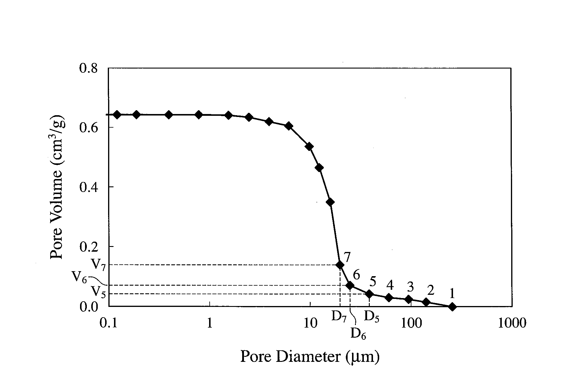
[0118]32.0 parts by mass of titania powder having a median diameter of 1.6 μm, 56.1 parts by mass of alumina powder having a median diameter of 5 μm, 3.0 parts by mass of silica powder having a median diameter of 20 μm, and 3.0 parts by mass of magnesia powder having a median diameter of 2 μm as ceramic material powders having an aluminum titanate composition, a molding aid, and 7.0 parts by mass of titanium-oxide-coated, hollow resin particles having a median diameter of 20 μm and sphericity of 0.92 as a pore-forming material were mixed, blended, and extruded to obtain a honeycomb structure molding having an outer diameter of 50 mm, a length of 90 mm, a cell wall thickness of 10 mil (0.25 mm), and a cell density of 300 cpsi (46.5 cells / cm2). After drying, the molding was machined to remove its peripheral portions, and sintered by a schedule comprising temperature elevation at a heating speed of 50° C. / hour from room temperature to 150° C., at a heating speed of 10° C. / hour from 150...
PUM
| Property | Measurement | Unit |
|---|---|---|
| median pore diameter D50 | aaaaa | aaaaa |
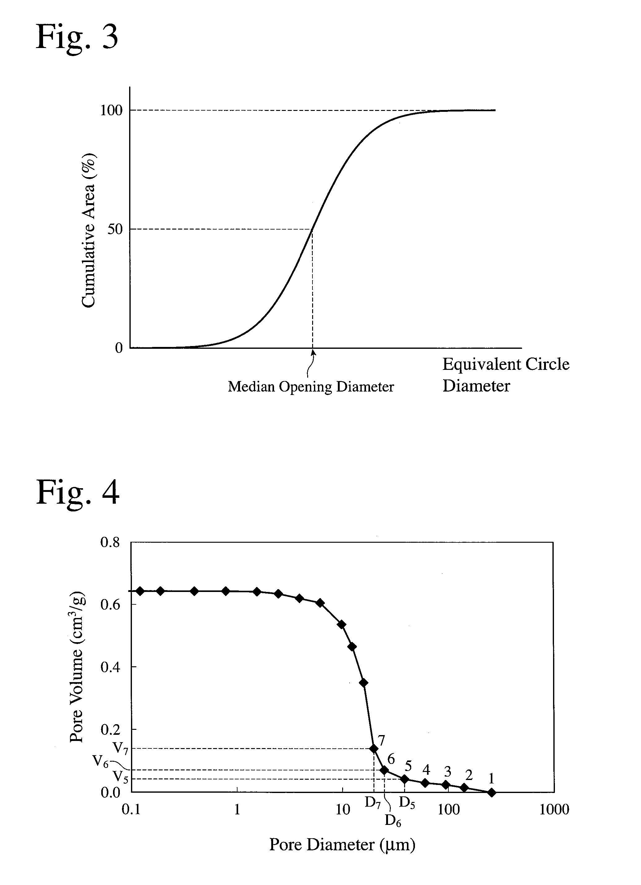
| median opening diameter d50 | aaaaa | aaaaa |
| circle diameters | aaaaa | aaaaa |
Abstract
Description
Claims
Application Information