Rotor for a synchronous reluctance machine

a synchronous reluctance machine and synchronous technology, applied in the direction of dynamo-electric machines, magnetic circuit rotating parts, magnetic circuit shape/form/construction, etc., can solve the problem that the rotor designed according to the conventional design principles still exhibits high torque ripple, and achieves the effect of improving the effect of torque ripple behaviour

Active Publication Date: 2014-01-28
ABB RES LTD
View PDF8 Cites 9 Cited by
  • Summary
  • Abstract
  • Description
  • Claims
  • Application Information

AI Technical Summary

Benefits of technology

[0018]A simulation model is necessary in order to effectively take advantage of the present invention. When a simulation model comprising a parameter δ for the q-axis pitch angle once is created, it is easy to execute simulations with different δ values in order to find an optimum value.
[0019]The simulation model may be configured to return a value corresponding to the torque ripple. δ is increased and / or decreased until at least one local minimum of the value corresponding to the torque ripple is found, and the q-axis pitch angle value is determined to correspond to the local minimum of the torque ripple. It is relatively easy to find out the behaviour of the torque ripple curve by a small number of simulations with discrete δ values, and it is logical to give the q-axis pitch angle a value δ that results to a minimum torque ripple.
[0020]The initial value of the q-axis pitch angle may be chosen to be δ=3*αm. Although the initial q-axis pitch angle value can be chosen arbitrarily, choosing δ=3*αm is a good starting point and gives an idea how the torque ripple behaviour is improved compared to the prior art solutions.

Problems solved by technology

However, despite the measures taken to decrease the torque ripple, rotors designed according to the conventional design principles still exhibit a high torque ripple.

Method used


Image

  • Rotor for a synchronous reluctance machine
  • Rotor for a synchronous reluctance machine
  • Rotor for a synchronous reluctance machine

Examples


Embodiment Construction

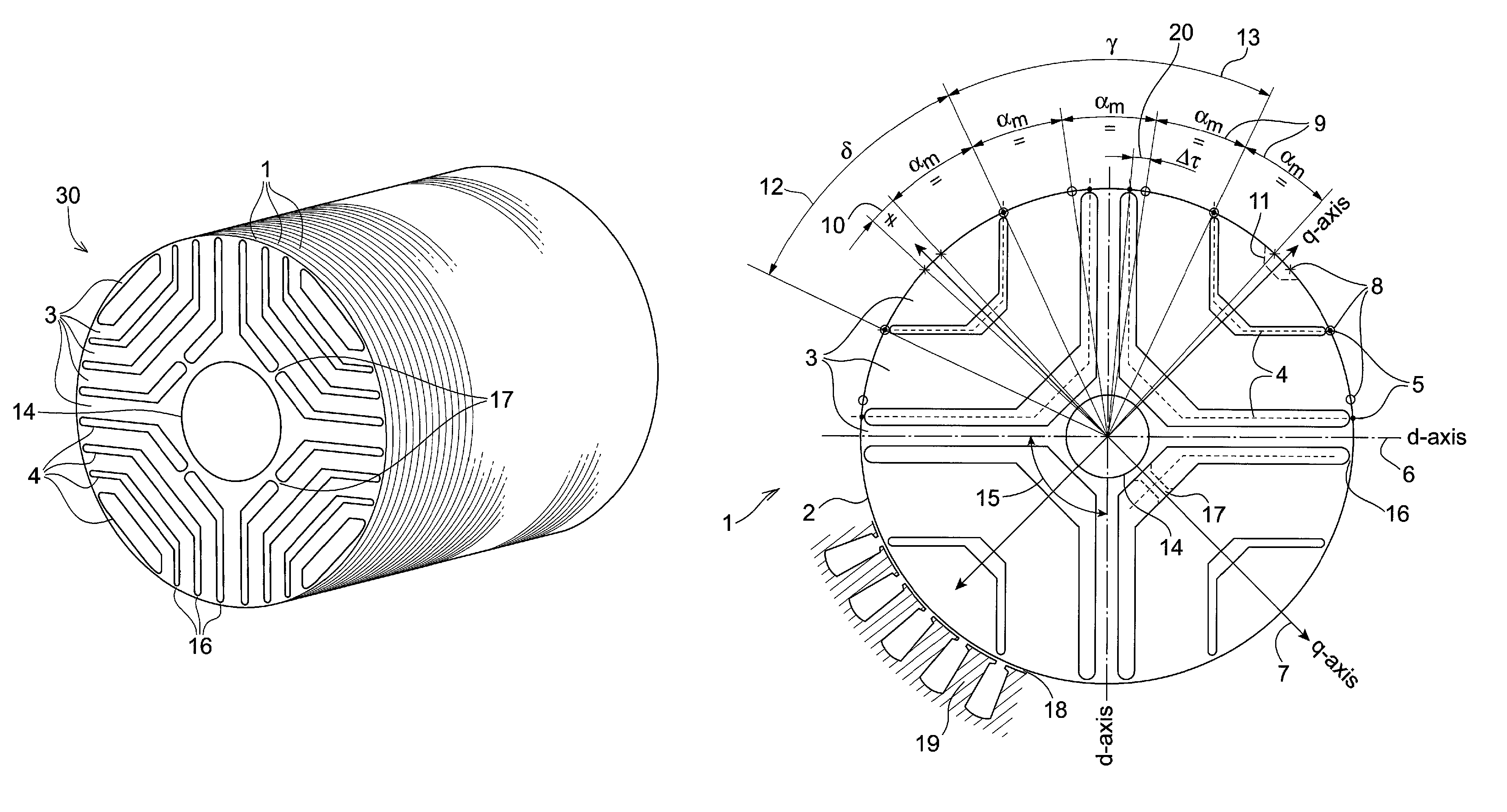
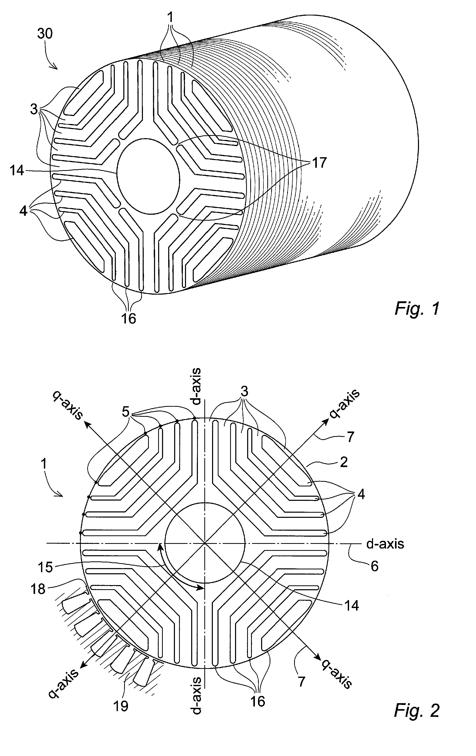
[0028]FIG. 1 shows a rotor 30 according to one embodiment of the invention, the rotor 30 essentially consisting of a stack of thin rotor discs 1.

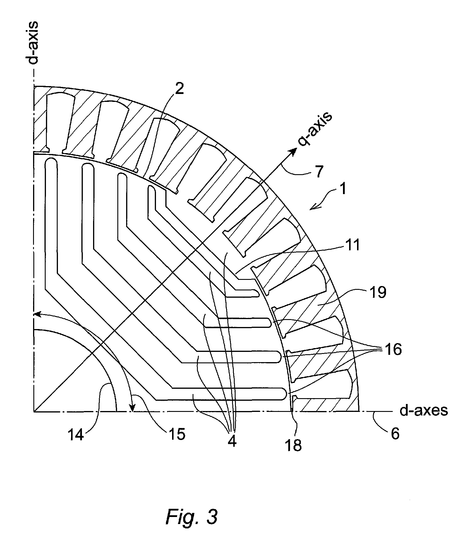
[0029]FIG. 2 shows a rotor disc 1 for a rotor 30 according to one embodiment of the invention. The depicted rotor disc 1 comprises four pole sectors 15, each pole sector 15 comprising five segments 3 made of a material with a high relative magnetic permeability. Each of the five magnetically permeable segments 3 has an arm-shaped form extending between two predetermined angular positions on the disc perimeter 2. Four insulating barriers 4 are intermittently disposed between the permeable segments 3 in a manner where an alternating pattern of magnetically permeable segments 3 and insulating barriers 4 are formed along the q-axes 7 of the rotor disc 1 from a central aperture 14 towards the disc perimeter 2. The insulating barriers 4 are separated from the air gap 18 between the rotor 30 and the stator 19 by tangential ribs 16. Optionally the ...


PUM


Abstract

A rotor for a synchronous reluctance machine wherein a torque ripple behaviour of the machine is optimized by altering the geometry of insulating barriers of the rotor. A q-axis pitch angle is used as a design variable instead of setting its value equal to the rest of the rotor slot pitches or binding its value to the stator slot pitch. The resulting rotor has a non-regular slot pitch across the q-axis and substantially regular slot pitch otherwise. Synchronous reluctance machines that employ rotor discs and rotor assemblies in accordance with the present invention may exhibit low torque ripple without sacrificing high torque values.

Description

CROSS-REFERENCE TO RELATED APPLICATIONS[0001]The present application is a continuation of pending International patent application PCT / EP2009 / 052930 filed on Mar. 12, 2009 which designates the United States, the content of which is incorporated herein by reference.FIELD OF THE INVENTION[0002]The present invention relates to a rotor for a synchronous reluctance machine, especially the geometry of the insulating barriers of the rotor and the geometry's effect on the torque ripple behaviour of the machine. The present invention further relates to a method of designing a rotor for a synchronous reluctance machine.BACKGROUND OF THE INVENTION[0003]Synchronous reluctance machines known in the art typically comprise stators with poly-phase windings forming a plurality of poles in a manner resembling the stator of an induction motor. The rotor assembly of the synchronous reluctance machine does normally not include electrical windings but has a number of poles in form of magnetically permeab...

Claims


Application Information

Patent Timeline
Patent Type & Authority Patents(United States)
IPC IPC(8): H02K19/02
CPCH02K1/246H02K29/03H02K1/24H02K19/10
Inventor MOGHADDAM, REZA, RAJABI
Owner ABB RES LTD
Why Eureka
Try Eureka