Manufacturing method of flow passage network and flow passage network using the same

a technology of flow passages and manufacturing methods, applied in the direction of hose connections, instruments, transportation and packaging, etc., can solve the problems of large flow loss, difficult smooth flow, and complex flow passage networks of small-scale bio-chips and human bodies, so as to reduce flow loss and increase energy efficiency of flow passages

Active Publication Date: 2014-02-04
POSTECH ACAD IND FOUND
View PDF6 Cites 4 Cited by
  • Summary
  • Abstract
  • Description
  • Claims
  • Application Information

AI Technical Summary

Benefits of technology

[0011]The present invention has been made in an effort to provide a manufacturing method of a flow passage network and a flow passage network using the same having advantages of minimizing energy loss occurring during flow.
[0023]As described above, according to the exemplary embodiments of the present invention, there are effects in which flow loss is reduced during fluid transport and the energy efficiency of flow passages increases by optimizing geometric factors of flow passages on the basis of biomimetic techniques and theoretical formulae of fluid mechanics. Further, it is effective in manufacturing microfluidics in which laminar flow with a low Reynolds number is dominant.

Problems solved by technology

Further, small-scale bio-chips and blood circulation systems of human bodies can also be complex forms of flow passage networks.
In this case, much flow loss occurs due to inefficiency of fluid transport.
Further, such flow passages cause an abnormal flow phenomenon such as flow separation and secondary flow due to inappropriate geometric factors, thereby making smooth flow difficult and increasing flow loss.
Most of all, in view of an entire flow passage system, flow loss causes a great deal of energy loss.
Therefore, a geometrically manufacturing method for improving an inefficient flow passage system is necessary.

Method used


Image

  • Manufacturing method of flow passage network and flow passage network using the same
  • Manufacturing method of flow passage network and flow passage network using the same
  • Manufacturing method of flow passage network and flow passage network using the same

Examples


Embodiment Construction

[0029]The present invention will be described more fully hereinafter with reference to the accompanying drawings, in which exemplary embodiments of the invention are shown. As those skilled in the art would realize, the described embodiments may be modified in various different ways, all without departing from the spirit or scope of the present invention. The drawings and description are to be regarded as illustrative in nature and not restrictive. Like reference numerals designate like elements throughout the specification.

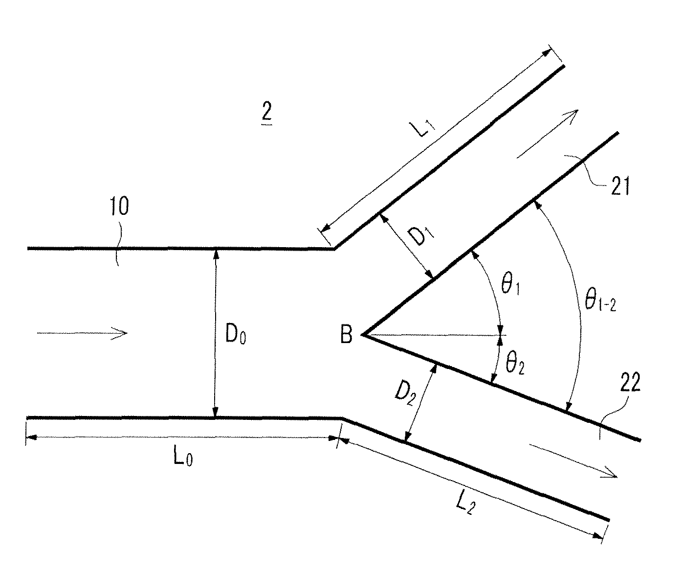
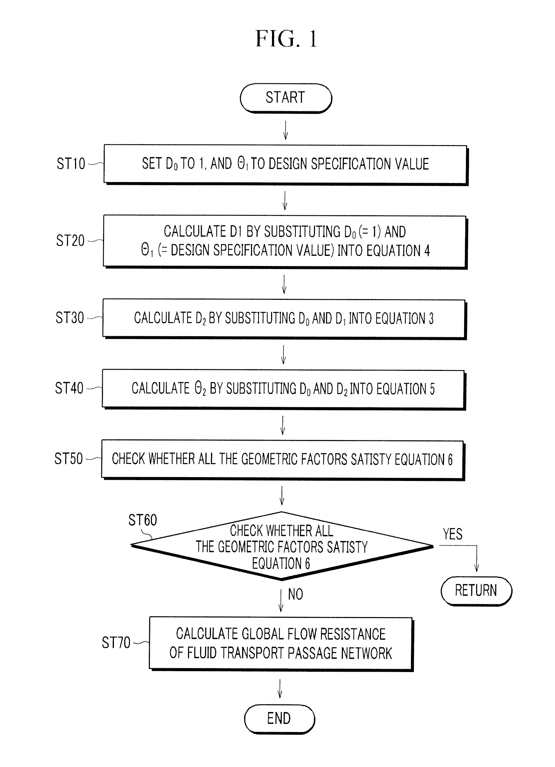
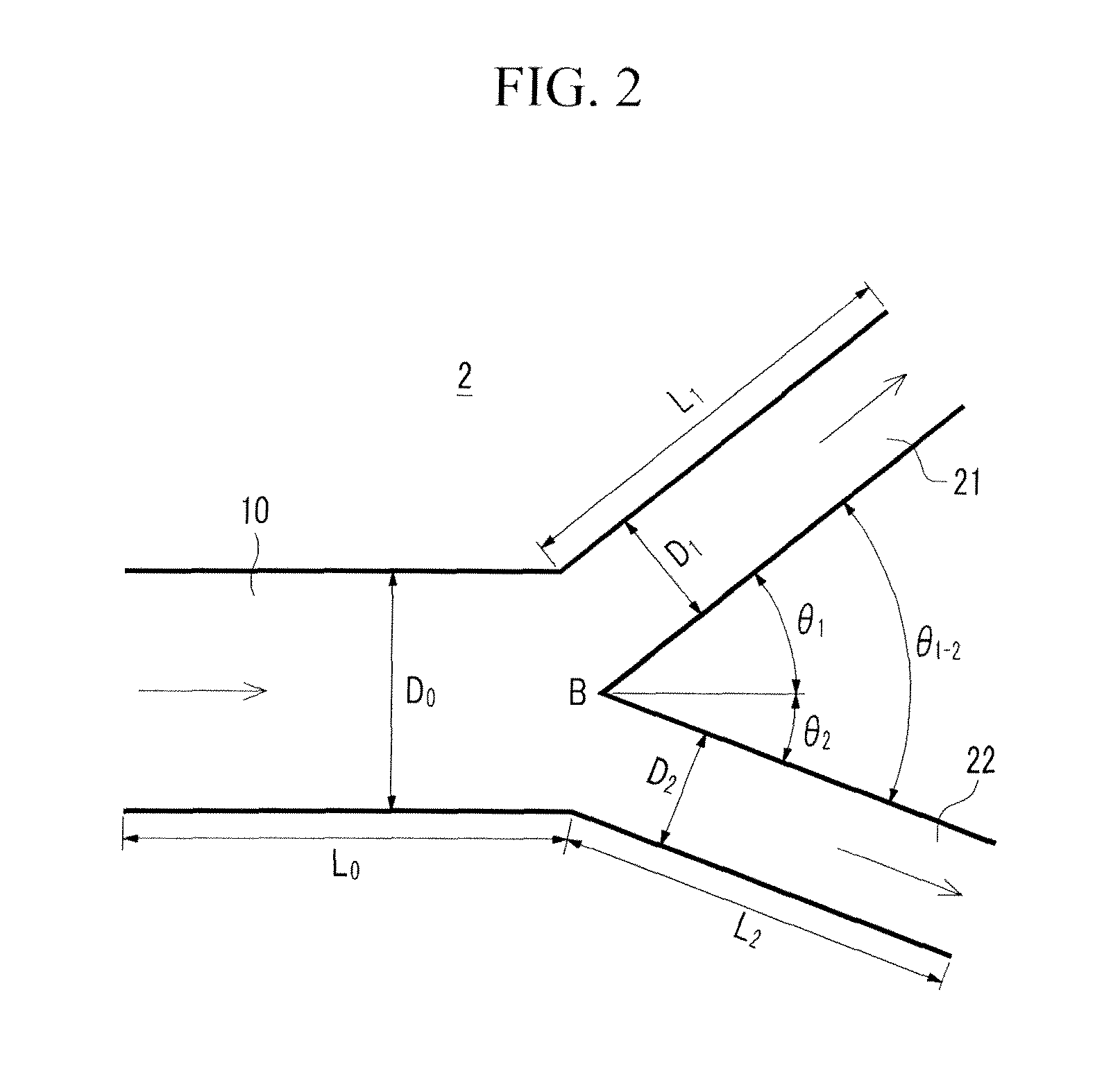
[0030]FIG. 1 shows a flowchart of a manufacturing method of a flow passage network (hereinafter referred to as “a manufacturing method” for convenience) according to an exemplary embodiment of the present invention, and FIG. 2 shows a schematic diagram of bifurcated branches applied to a flow passage network manufactured according to an exemplary embodiment of the present invention.

[0031]Referring to FIGS. 1 and 2, an exemplary embodiment shows a method of optimi...


PUM

PropertyMeasurementUnit
bifurcation angleaaaaaaaaaa
radiusaaaaaaaaaa

Abstract

An exemplary embodiment of the present invention relates to a manufacturing method of a flow passage network and a flow passage network for minimizing energy loss occurring during fluid flow, and there are effects in which flow loss is reduced during fluid transport and the energy efficiency of flow passages increases by optimizing geometric factors of flow passages on the basis of biomimetic techniques and theoretical formulae of fluid mechanics. Further, it is effective in manufacturing microfluidics in which laminar flow with a low Reynolds number is dominant.

Description

CROSS-REFERENCE TO RELATED APPLICATION[0001]This application claims priority to and the benefit of Korean Patent Application No. 10-2009-0109301 filed in the Korean Intellectual Property Office on Nov. 12, 2009, the entire contents of which are incorporated herein by reference.BACKGROUND OF THE INVENTION[0002](a) Field of the Invention[0003]The present invention relates to a manufacturing method of a flow passage network and a flow passage network using the same, and more particularly, to a manufacturing method of a flow passage network and a flow passage network for minimizing energy loss occurring during fluid flow.[0004](b) Description of the Related Art[0005]Fluid flow systems have been developed throughout the history of mankind over a long period of time. For example, there are agricultural irrigation canals, urban water and sewage passages, transport passage systems of industrial estates, etc. Further, small-scale bio-chips and blood circulation systems of human bodies can al...

Claims


Application Information

Patent Timeline
Patent Type & Authority Patents(United States)
IPC IPC(8): F16C1/06F16L31/02F16C1/02F16L47/32
CPCF16L41/023F16L41/02Y10T137/85938Y10T137/8593Y10T137/2224F16L25/14F16L55/02
Inventor LEE, SANG-JOONLEE, JUNG-YEOP
Owner POSTECH ACAD IND FOUND
Why Eureka
Try Eureka