
Miniature safe and arm mechanisms for fuzing of gravity dropped small weapons

a technology of gravity drop and arm mechanism, which is applied in the direction of mechanical fuzes, electric fuzes, weapons, etc., can solve the problems that the same cannot be said regarding ordnance technologies that support system functional capabilities, and the simple miniaturization of subsystems alone cannot achieve the desired effect of effective fuzing for smaller weapons, so as to reduce collateral damage, low cost, and piezoelectric

Active Publication Date: 2014-02-11
OMNITEK PARTNERS LLC
View PDF16 Cites 6 Cited by
  • Summary
  • Abstract
  • Description
  • Claims
  • Application Information

AI Technical Summary

Benefits of technology

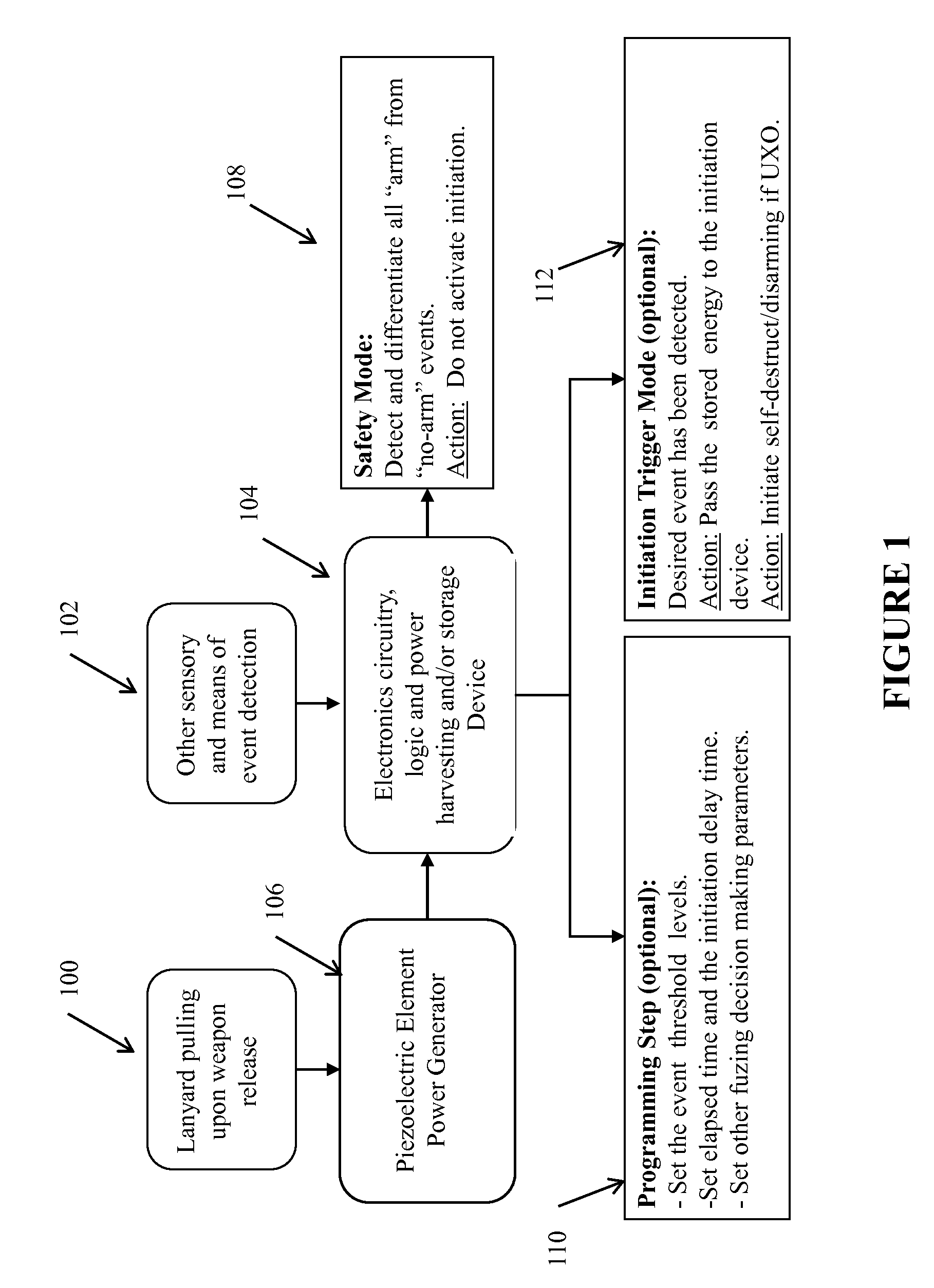
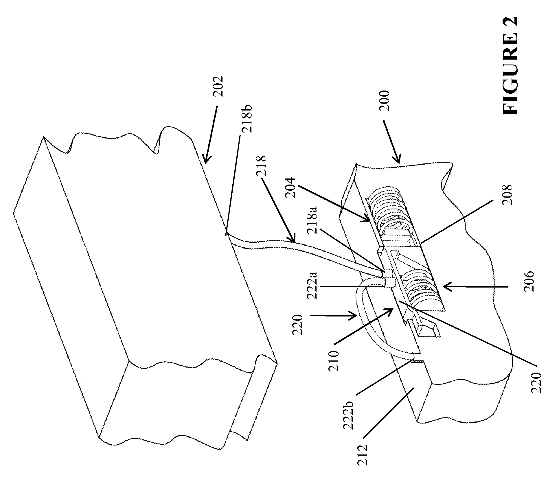
The patent text describes the use of piezoelectric elements to provide electrical energy and detect and determine the impact force level and direction of a target, which can be used for various fuzing purposes such as powering fuzzing electronic and logics circuitry. The piezoelectric-based generators are small and low cost, and can be produced using standard manufacturing techniques and components. The overall packaging electronic and logics circuitry and power generation devices can also be small and low cost. This makes them highly suitable for weapon systems dropped from almost any altitude, even very high and very low altitudes, and can help reduce collateral damage and create safer and more efficient weapons systems.

Problems solved by technology

However, the same cannot be said regarding ordnance technologies that support system functional capabilities, for example for the case for fuzing.
It is important to note that simple miniaturization of subsystems alone will not achieve the desired goal of effective fuzing for smaller weapons.

Method used


Image

  • Miniature safe and arm mechanisms for fuzing of gravity dropped small weapons
  • Miniature safe and arm mechanisms for fuzing of gravity dropped small weapons
  • Miniature safe and arm mechanisms for fuzing of gravity dropped small weapons

Examples


first embodiment

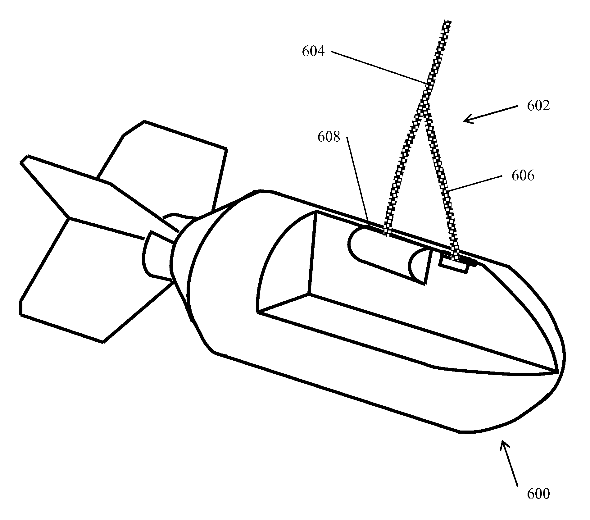
[0103]Referring now to FIG. 16, there is shown a cut-away schematic of gravity dropped weapon 600 having a device 602 to differentiate air-drops from accidental ground-drops prior to lanyard pull is shown in FIG. 16. In the device 602, a lanyard 604 is provided connecting the weapon 600 to a platform (such as an airframe of an airplane) from which it is dropped. The lanyard 604 includes a connected portion, such as a short cable 606 attached to the lanyard 604 such that as the lanyard 604 is pulled (due to being dropped from the platform), it activates a power generation device, such as a dynamo-type or piezoelectric-type event detection and power generation device 608 (such as those described above). The pulling of the lanyard 604 also results in the pulling of the second short cable 606 out, thereby activating an air-velocity sensor. Although shown as a single lanyard having a short cable 606, two separate lanyards may also be provided (one to activate the power generation device ...

second embodiment

[0106]In a second embodiment, as shown in FIG. 18, the device 602a includes the short cable 606 is similarly attached to the lanyard 604 such that as it is pulled and activates the dynamo-type or piezoelectric-type event detection and power generation device 608 it would also pull the second short cable 606. As shown in FIGS. 19a and 19b (prior to lanyard pull), the split lanyard 604, 606 actuates the dynamo-type or piezoelectric-type generator and removes a small plug 612, exposing a port 614 which can use the Bernoulli Effect to sense velocity.

[0107]In an alternative version, the first and second embodiments are “combined” to provide an effectively “omni-directional” airstream velocity detector as shown in FIGS. 20a and 20b. In the alternative version, the device 602b includes an airstream detector 616, includes a sensor portion 618 fixed to the weapon 600 and a cover portion 620 releasably mounted to the sensor portion 618 and attached to an end of the short cable 606. The sensor...


PUM


Abstract

Methods and devices for differentiating an actual air drop of a gravity dropped weapon from an accidental drop of the weapon onto a surface. The method including: connecting a first end of at least one lanyard to an airframe; releasably connecting a second end of the at least one lanyard to a power generation device such that release of the second end with the power generation device initiates power generation by the power generation device; and releasably connecting a third end of the at least one lanyard to at least a portion of an air velocity sensor such that release of the third end one of activates or exposes the air velocity sensor to an air stream; and differentiating the actual air drop from the accidental drop based at least on a detection of an air velocity by the air velocity sensor.

Description

CROSS-REFERENCE TO RELATED APPLICATIONS[0001]This application is a Continuation-In-Part application of U.S. application Ser. No. 12 / 983,301, filed on Jan. 1, 2011, which claims benefit to U.S. Provisional Application No. 61 / 303,294 filed on Feb. 10, 2010, the entire contents of each of which is incorporated herein by reference. This application is related to U.S. patent application Ser. No. 12 / 606,893 filed on Oct. 27, 2009, the entire contents of which is incorporated herein by reference.GOVERNMENT RIGHTS[0002]This invention was made with Government support under contract FA8651-10-C-0145 awarded by the United States Air Force. The Government has certain rights in the invention.BACKGROUND OF THE INVENTION[0003]1. Field of the Invention[0004]The present invention relates generally to small weapon systems, and more particularly, to methods for enabling safe / arm functionality within small weapons.[0005]2. Prior Art[0006]All weapon systems require fuzing systems for their safe and effe...

Claims


Application Information

Patent Timeline
Patent Type & Authority Patents(United States)
IPC IPC(8): F42C11/00
CPCF42B25/00F42C14/06B64D1/06F42C15/20F42C15/005
Inventor RASTEGAR, JAHANGIR, S.
Owner OMNITEK PARTNERS LLC
Learn More