Intraocular lens

a technology of intraocular lens and lens body, applied in the field of intraocular lens, can solve the problems of deteriorating contrast of such lens, reducing the visible range of the object, so as to and suppress deterioration in contrast

Active Publication Date: 2014-02-11
HOYA CORP
View PDF20 Cites 13 Cited by
  • Summary
  • Abstract
  • Description
  • Claims
  • Application Information

AI Technical Summary

Benefits of technology

[0022]According to the above-described means, it is possible to obtain an intraocular lens in which deterioration in contrast is suppressed even when the optical axis of the intraocular lens is decentred from the optical axis of the eyeball when the intraocular lens is inserted into the eye, by employing such a power distribution as respectively having at least one positive power deviation region having a larger power than that represented by the reference power distribution and one negative power deviation region having a smaller power than that represented by the reference power distribution in the central region of the intraocular lens. In this case, it is preferable that the central region have a substantially circular shape centering around the optical axis having a radius not less than 0.7 mm and not more than 1.75 mm. If the radius is smaller than 0.7 mm or larger than 1.75 mm, the function for suppressing deterioration in contrast caused by an optic decentration is not sufficient. More preferably, the radius should be within a range not less than 1.2 mm and not more than 1.5 mm. Further, it is preferable that the power deviation amounts from the reference power of the positive power deviation region or the mean value thereof be not less than 0.1 diopter and not more than 0.8 diopter, and the power deviation amounts from the reference power of the negative power deviation region or the mean value thereof be not less than 0.1 diopter and not more than 0.8 diopter. If the radius is smaller than 0.1 diopter, the function for suppressing deterioration in contrast caused by an optic decentration is not sufficient, and if the radius is larger than 0.8 diopter, a clear image cannot be obtained. With general environmental illumination being taken into consideration, more preferably, the radius should be within in a range not less than 0.2 diopter and not more than 0.5 diopter. Notably, it is found that deterioration in contrast is suppressed also when the intraocular lens is tilted when it is inserted into the eye, as well as when there is an optic decentration.

Problems solved by technology

As a result, despite an increased visible range, contrast of such lens is deteriorated (for example, see Patent Document 1).
Such pupil diameter is greatly affected by the spherical aberration such that the contrast of an object is deteriorated, which may be dangerous for driving a car.
However, they have an disadvantage that they provide a smaller visible range compared with the spherical lens due to smaller depth of focus.

Method used


Image

  • Intraocular lens
  • Intraocular lens
  • Intraocular lens

Examples


embodiment 1

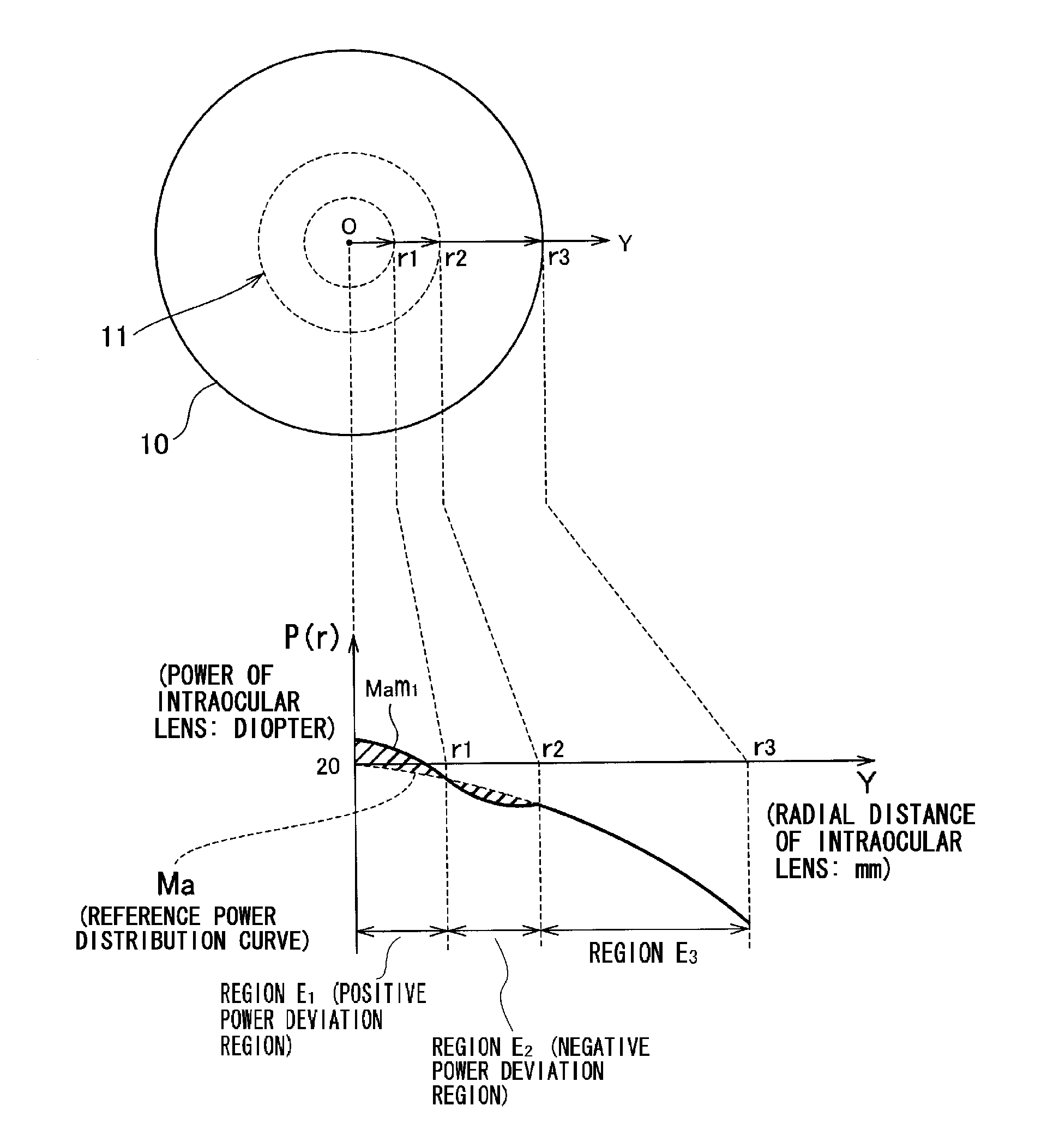
[0028]As shown in FIG. 1, with respect to the reference power distribution curve Ma, the power distribution of the intraocular lens 10 according to this embodiment is such that: a power is larger than that represented by the reference power distribution in the region E1 inside the region 11 in the vicinity of the center of the intraocular lens 20, and the region E1 serves as the positive power deviation region; and a power is smaller than that represented by the reference power distribution the in region E2 inside the region 11 in the vicinity of the center of the intraocular lens 20, and the region E2 serves as the negative power deviation region. The following equation is obtained by polynomial approximation of the power distribution of the intraocular lens according to the

P(r)=a0+a1r2+a2r4+ . . . +an-1r2(n-1)+anr2n  Eq. 1

[0029]n=8

[0030]

iai020.312969771−1.4587525920.7612070330.032913694−0.1520333350.052604246−0.0081295670.000606758−0.00001778

[0031]As shown in FIG. 3, the power dis...

embodiment 2

[0040]FIG. 11 is a graph showing the power distribution Mbm1 of the intraocular lens the power distribution of the spherical intraocular lens, and the reference power distribution Mb. Herein, the reference power distribution curve Mb employs the power distribution in which the powers are the same as those of the spherical intraocular lens in the vicinity of the optical axis, and as to cancel the spherical aberration of the cornea, the powers are decreased with distance closer to the outer periphery. That is, the reference power distribution curve Mb does not employ the power distribution which cancels the spherical aberration of the cornea in the vicinity of the optical axis. In addition, although the reference power distribution curve Mb employs the power distribution so as to cancel the spherical aberration of the cornea in other regions, the power distribution does not perfectly cancel the spherical aberration of the cornea, unlike the reference power distribution Ma.

[0041]FIG. ...


PUM


Abstract

An intraocular lens in which deterioration in contrast is suppressed even when the optical axis of the intraocular lens is decentered from the optical axis of the eyeball when the intraocular lens is inserted into the eye while the advantage of a conventional aberration reduction type intraocular lens that the image is seen clearly is sustained by employing such a power distribution as respectively having at least one positive power deviation region (E1) having a power larger than that represented by the reference power distribution and at least one negative power deviation region (E2) having a power smaller than that represented by the reference power distribution in the central region of the intraocular lens assuming that a power distribution being set to cancel the spherical aberration of cornea when the intraocular lens is inserted into the eye is the reference power distribution.

Description

TECHNICAL FIELD[0001]The present invention relates to an intraocular lens which enables suppressing contrast deterioration due to an optic decentration which occurs when the intraocular lens is inserted into an eye.BACKGROUND[0002]An intraocular lens is inserted, for vision correction, into an eyeball after removing the crystalline lens due to cataract or the like. A spherical design is the mainstream of the current optical designs for an intraocular lens, because the design has many functions required for an intraocular lens moderately, is easy to manufacture, and is convenient for managing powers. However, an intraocular lens is also being developed with attention being paid to a specific function and with an aim for enhancing the function. The technological trends for enhancement of such specific function can be classified into two types. The first trend is directed to enable an eye to see both near objects and distance objects. The second trend is directed to enable an eye to se...

Claims


Application Information

Patent Timeline
Patent Type & Authority Patents(United States)
IPC IPC(8): A61F2/16
CPCA61F2/1613A61F2/1624A61F2/1637A61F2/1618A61F2002/1699A61F2/164
Inventor SANGER, DEMASLAWU, TJUNDEWO
Owner HOYA CORP
Why Eureka
Try Eureka