Assembly comprising a measuring scale attached to a substrate and method for holding a measuring scale against a substrate

a technology of measuring scales and substrates, which is applied in the direction of instruments, applications, and converting sensor outputs, etc., can solve the problems of easy interference of connection, increased problems, and so as to avoid large-area contact and avoid short-period errors in length in the plane of measuring graduations. , the effect of high measurement accuracy

Active Publication Date: 2014-02-18
DR JOHANNES HEIDENHAIN GMBH
View PDF9 Cites 2 Cited by
  • Summary
  • Abstract
  • Description
  • Claims
  • Application Information

AI Technical Summary

Benefits of technology

[0018]With the present invention, the attainable advantages of pneumatic suction are exploited in that the most homogeneous possible surface forces are exerted as holding forces, yet at the same time the disadvantages of large-area contact are avoided because many supports separate from one another are provided.
[0019]The surface smoothness—even of a large-area scale—is preserved or is not interfered with, since interfering media can be deposited in the spaces formed by the spaced-apart supports. By the provision according to the present invention, short-period errors in length in the plane of the measuring graduation are avoided, and high measurement accuracy is ensured.
[0020]In the measurement mode, the scale is secured stably on the substrate, which means great rigidity in the measurement direction and also perpendicular to the plane of the measuring graduation.
[0021]With the present invention, in contrast to optical contact bonding, it is ensured that the holding forces generated by the pneumatic suction develop uniformly over the entire surface of the scale. This is achieved by providing that an optical contact bonding element at the contact faces between the scale and the substrate is avoided. Thus there is also the advantage that the contact faces do not have to be machined with high precision; polished surfaces are sufficient.

Problems solved by technology

The problem here is that when the scale rests on the substrate, the connection can easily be interfered with by contaminants or the development of air bubbles in the space between the scale and the substrate.
These problems lead to changes in length over time and location of the measuring graduation of the scale, which in turn cause errors in the position measurement.
This problem occurs to an increased degree in relatively large-area scales.
In large-area optical contact bonding elements, the problem is that a disturbance in the contact face can detach the entire optical contact bonding element, because the detachment spreads.
Although this embodiment does ensure a secure fastening of the scale to a substrate, nevertheless a stress-free contact pressure that is homogeneous over the entire measuring graduation plane is only poorly attained in this way.

Method used


Image

  • Assembly comprising a measuring scale attached to a substrate and method for holding a measuring scale against a substrate
  • Assembly comprising a measuring scale attached to a substrate and method for holding a measuring scale against a substrate
  • Assembly comprising a measuring scale attached to a substrate and method for holding a measuring scale against a substrate

Examples


Embodiment Construction

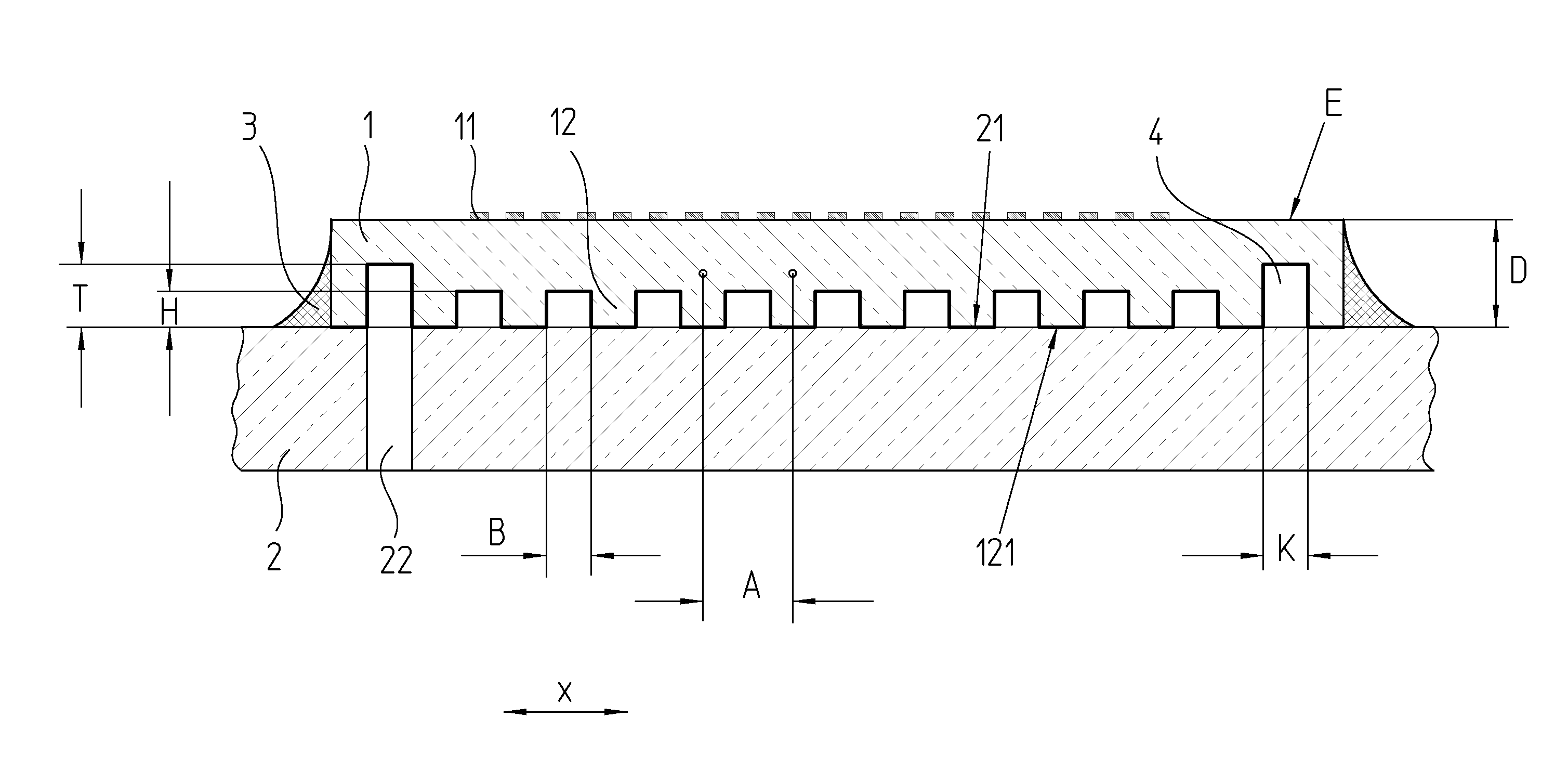
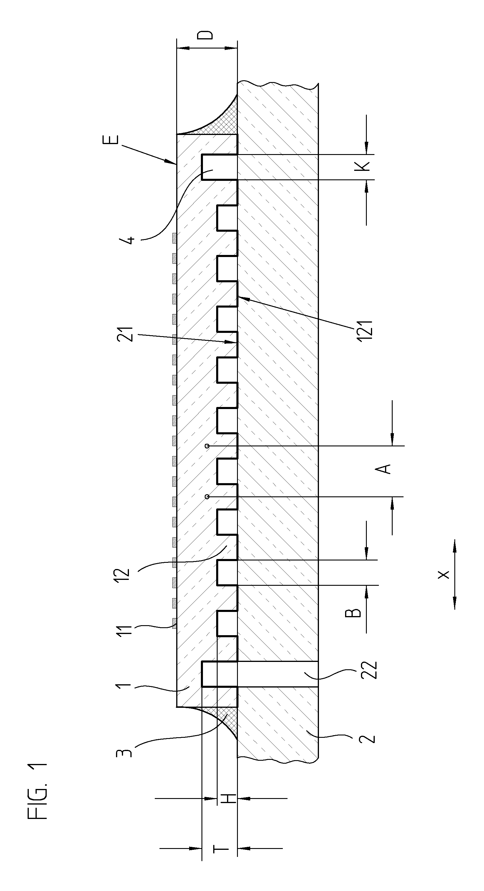
[0030]A first exemplary embodiment of the present invention will be explained in conjunction with FIGS. 1 through 3. In it, a scale 1 of glass or glass ceramic (such as the glass material sold under the trademark ZERODUR) with a measuring graduation 11 is shown. The measuring graduation 11 is an incremental graduation, which is scanned in the measurement direction X by a scanning unit, not shown, for generating position-dependent scanning signals during a position measuring process. The measuring graduation 11 can be a reflective amplitude grating or a phase grating, wherein in a known manner measuring graduation 11 provides high-precision interferential position measurement. During such position measurement, the scale 1 is held on a substrate 2 by pneumatic suction. Pneumatic suction is defined to be clamping by a vacuum, also known as vacuum clamping. This substrate 2 preferably includes a material which has the same thermal expansion as the scale 1. The mean coefficient of therma...


PUM

PropertyMeasurementUnit
heightaaaaaaaaaa
temperatureaaaaaaaaaa
thicknessaaaaaaaaaa

Abstract

An assembly including a substrate and a scale held on the substrate, wherein the scale has a measuring graduation, and the scale is held on the substrate by pneumatic suction. The scale is braced on the substrate via two-dimensionally distributed, spaced-apart supports, which are disposed facing a measurement area defined by the measuring graduation and wherein adjacent ones of the supports are spaced apart from one another at a mutual period that is less than a thickness of the scale. In addition, the supports have a structure such that a connection by optical contact bonding between the supports and the scale and/or between the supports and the substrate is prevented at least in the measurement area. A space between the scale and the substrate is sealed off from surroundings by a sealing structure.

Description

[0001]Applicants claim, under 35 U.S.C. §§120 and 365, the benefit of priority of the filing date of Feb. 23, 2010 of a Patent Cooperation Treaty patent application, copy attached, Serial Number PCT / EP2010 / 052239, filed on the aforementioned date, the entire contents of which are incorporated herein by reference, wherein Patent Cooperation Treaty patent application Serial Number PCT / EP2010 / 052239 was not published under PCT Article 21(2) in English.[0002]Applicants claim, under 35 U.S.C. §119, the benefit of priority of the filing date of Apr. 2, 2009 of a German patent application, copy attached, Serial Number 10 2009 002 142.6, filed on the aforementioned date, the entire contents of which is incorporated herein by reference.BACKGROUND OF THE INVENTION[0003]1.Field of the Invention[0004]For measuring the relative position of two machine parts, a scale has to be secured to one of the machine parts, and a scanning unit has to be secured to the other of the machine parts movable rela...

Claims


Application Information

Patent Timeline
Patent Type & Authority Patents(United States)
IPC IPC(8): G01D5/26G01B11/02G01D5/347
CPCG01D5/34707Y10T29/49826
Inventor SPECKBACHER, PETERWEIDMANN, JOSEFHOLZAPFEL, WOLFGANG
Owner DR JOHANNES HEIDENHAIN GMBH
Why Eureka
Try Eureka