Dispensing device, particularly for domestic appliances

a technology for dispensing devices and domestic appliances, which is applied in the direction of coin-freed apparatus, pile separation, washing apparatus, etc., can solve the problems of lack of long-term reliability, complex construction, and even more complicated devices of this type, and achieves simple and relatively compact structure, precise and reliable operation, and convenient use for users

Active Publication Date: 2014-02-18
ELTEK
View PDF10 Cites 20 Cited by
  • Summary
  • Abstract
  • Description
  • Claims
  • Application Information

AI Technical Summary

Benefits of technology

[0009]The present invention proposes to indicate a new long-life dispensing device for substances or products to be delivered in doses having a simple and relatively compact structure, and being precise and reliable in operation and easy for a user to use.

Problems solved by technology

The known devices of the type indicated—besides being generally cumbersome—are subject to malfunctions due essentially to the inherent characteristics of powdered detergents; these detergents are negatively affected by the moisture which develops inside the dishwasher during each washing cycle, with lumps consequently forming over time; also the vibrations caused by the dishwasher's operation, however slight, can give rise to stratification in the mass of the powdered detergent, which fact has negative effects on the quality of washing (in practice, vibrations cause some components of the detergent to tend to accumulate at the bottom of the hopper-shaped container, and others at the top thereof).
Devices of this type are even more complicated, bulky and expensive.
This solution is constructionally complicated and lacking in long-term reliability, also in view of the need to provide the movable metering member with a plurality of gaskets, which have the function of operating a seal onto the surface of the stationary container, and which are therefore subject to deterioration over time, but cannot be easily replaced.
Filling and cleaning the compartments is relatively inconvenient to perform; any incrustations in the protected zone can cause operating problems for the device, which has no removable or replaceable parts.

Method used


Image

  • Dispensing device, particularly for domestic appliances
  • Dispensing device, particularly for domestic appliances
  • Dispensing device, particularly for domestic appliances

Examples


first embodiment

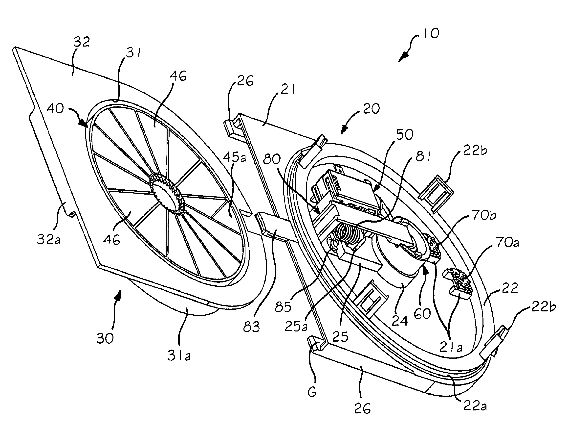
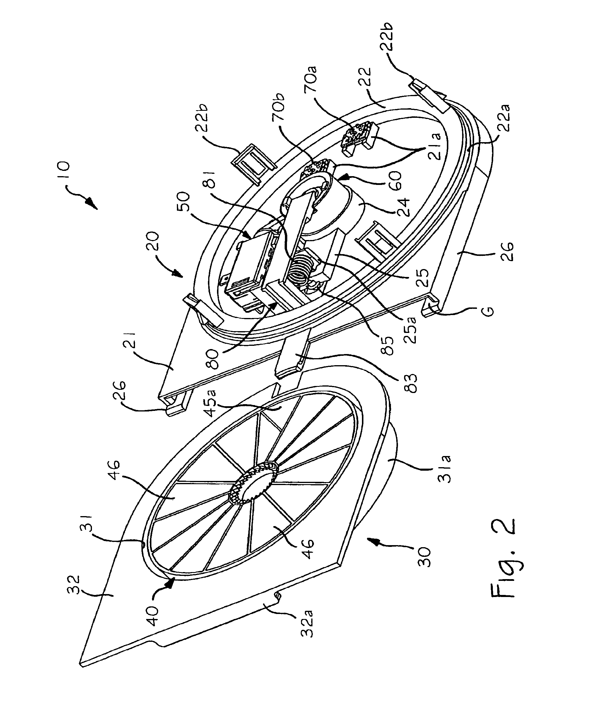
[0079]Fixed body 20 has associated thereto electrical actuation means, designed to be connected or interfaced with a respective control system, for the purpose of managing operation thereof; in the first embodiment these means consist of a thermoelectric actuator 50, whose type and operation are known per se, having a linearly movable shaft 51. The above-mentioned control system preferably consists of the same control system of the machine 1, but in possible alternative implementations the device according to the invention can be equipped with its own dedicated electronic control and / or detection circuit.

[0080]A transmission system 60 is associated to the body 20, arranged for transferring an actuating force generated in a controlled manner by means of actuator 50 to the magazine 40, in order to cause a movement thereof; as will become clear later, this movement is provided in order to make possible delivery of at least one dose of a substance or product, such as a detergent, contai...

second embodiment

[0131]In the case of the second embodiment, device 10 is equipped with an actuator of a different type from the previous one, and in particular a reversible electric motor, possibly with a reduction gear, and a transmission system with automatic switching from the inoperative to the operative condition, and vice versa, i.e., not requiring a manual switching device.

[0132]The above-mentioned motor, indicated by 50′, comprises a rotating actuation shaft 51′, at the distal end of which there is associated a transmission element 52, such as an endless screw, said shaft being substantially perpendicular to the axis of rotation of magazine 40. The transmission system further comprises a member 61′ which, as can be seen in FIG. 21, is of substantially similar construction to member 61 of the first embodiment, and for this purpose comprises the axial grooves 63 and the upper groove 64. The coupling element also, indicated by 66′, is of similar design to element 66 of the first embodiment; in...

fourth embodiment

[0163]FIGS. 32-34 illustrate a fifth inventive embodiment, similar to the fourth embodiment, but using a different type of actuator and a different transmission system.

[0164]This embodiment provides for the use of an electric motor 50″, possibly incorporating a reduction gear, having a shaft 51″ substantially coaxial with the axis of rotation of magazine 40, and a tubular transmission member 61″, whose body has an upper flanged part 61a″, designed to rest on the upper end of seat 24 of the fixed body 20′, and a lower cylindrical portion 61b″, capable of insertion into the above-mentioned seat 24; cylindrical portion 61b″ has at its lower edge a series of teeth 67′, designed to cooperate with the teeth of the magazine, which are here indicated by 47′. Inside the cylindrical portion 61b″ a central seat 61c″ is formed, with a closed bottom, capable of receiving a spring 62″ and an end section of shaft 51a″ of motor 50″, the seat and the shaft being of substantially complementary sectio...


PUM


Abstract

A long-life substance dispensing device for a washing machine, particularly a dishwasher, comprises: —a body (20′, 30′) designed to be sealingly fixed to a structure of the washing machine, —a support means (40) adapted to contain a total amount of a substance sufficient for performing a plurality of washing cycles, —an actuation system (47′, 50″, 61″) which is electrically controllable for causing delivery of at least one dose of the substance contained in the support means (40). The actuation system (47′, 50″, 61″) comprises at least one drive element and one driven element (47′) capable of cooperating to obtain the delivery. The actuation system (47′, 50″, 61″) is arranged for being able to take on an operative condition, wherein the drive element (61″) is operatively coupled with the driven element (47′), and an inoperative condition, wherein the drive element (61″) is decoupled from the driven element (47′).

Description

[0001]This application is the U.S. national phase of International Application No. PCT / IB2008 / 002131 filed 8 Aug. 2008, which designated the U.S. and claims priority to Italy Application No. TO2007A000598 filed 10 Aug. 2007, the entire contents of each of which are hereby incorporated by reference.FIELD OF THE INVENTION[0002]The present invention refers to dispensing devices arranged to contain and deliver a plurality of doses of at least one substance or product. The preferred application of the invention is in the field of long-life dispensers for domestic washing machines, i.e., dispensers arranged for retaining and delivering an amount of a washing agent sufficient for carrying out several operating cycles of the respective washing machine. The invention also has an advantageous application in the case of appliances for domestic use other than washing machines, and in hydraulic appliances in general, in which there is a need for selectively delivering individual doses of a total...

Claims


Application Information

Patent Timeline
Patent Type & Authority Patents(United States)
IPC IPC(8): B65H1/00D06F35/00D06F3/02A24F15/04B67D7/84D06F29/00B08B3/00G07F11/46
CPCD06F39/026A47L15/4454A47L15/4463A47L15/4472D06F58/203
Inventor GADINI, COSTANZOGAJ, RENATOMORO, MARCOHOUSMEKERIDES, CHRIS EFSTATHIOS
Owner ELTEK
Why Eureka
Try Eureka