
Mask pattern forming method and device, and method of producing optical disk

Inactive Publication Date: 2006-05-02
SONY CORP
View PDF7 Cites 4 Cited by
  • Summary
  • Abstract
  • Description
  • Claims
  • Application Information

AI Technical Summary

Benefits of technology

[0017]In view of the above-described problems, it is an object of the present invention to provide a method of and a device for forming a mask pattern, which allow more precise and more reliable recording operations to be carried out in a shorter time, and which provide more flexibility so that, for example, a recording operation can be carried out with corrections flexibly made in correspondence with a process condition. It is another object of the present invention to provide a method of producing an optical disk which uses the mask pattern formed in the mask pattern forming method and device, which does not require high-precision and expensive devices, and which does not require time to carry out

Problems solved by technology

This makes it necessary to use an expensive and high-precision machine.
When a pit recording disk, such as a compact disk-read only memory (CD-ROM) or a digital video disk-read only memory (DVD-ROM), is used, the conventional laser cutting operation takes a very long time to complete because the pits of the disk are irradiated with and exposed to laser one pit at a time.
Due to unstable process factors such as development conditions, slight changes in the focus servo operation, differences in the laser exposure amount caused by the sizes of pits, etc., a theoretical controlling operation of the laser power alone does not necessarily result in the formation of ideal pits as a result of linear speed and advancing conditions.

Method used


Image

  • Mask pattern forming method and device, and method of producing optical disk
  • Mask pattern forming method and device, and method of producing optical disk
  • Mask pattern forming method and device, and method of producing optical disk

Examples


Embodiment Construction

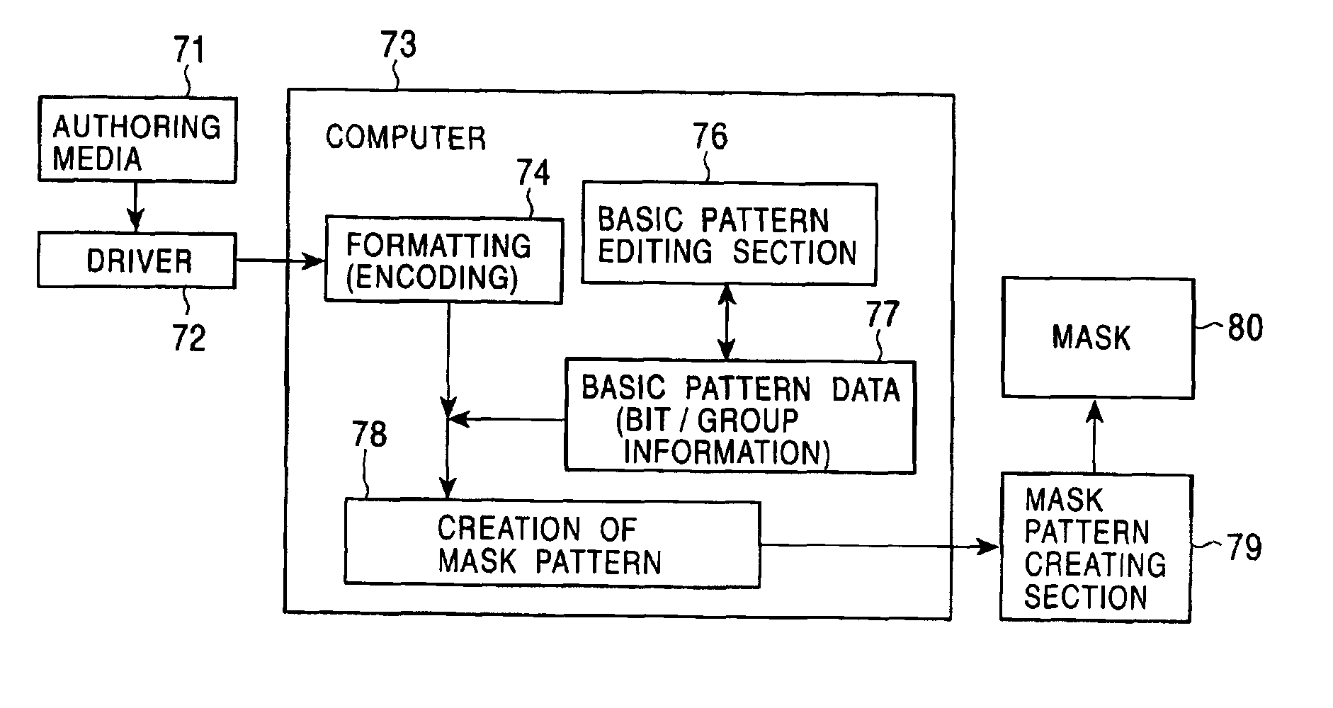
[0036]Hereunder, a description of a preferred embodiment of the method of producing an optical disk in accordance with the present invention will be given with reference to the drawings. In this method, a mask pattern formed in a mask pattern forming method of the present invention is used to produce an optical disk.

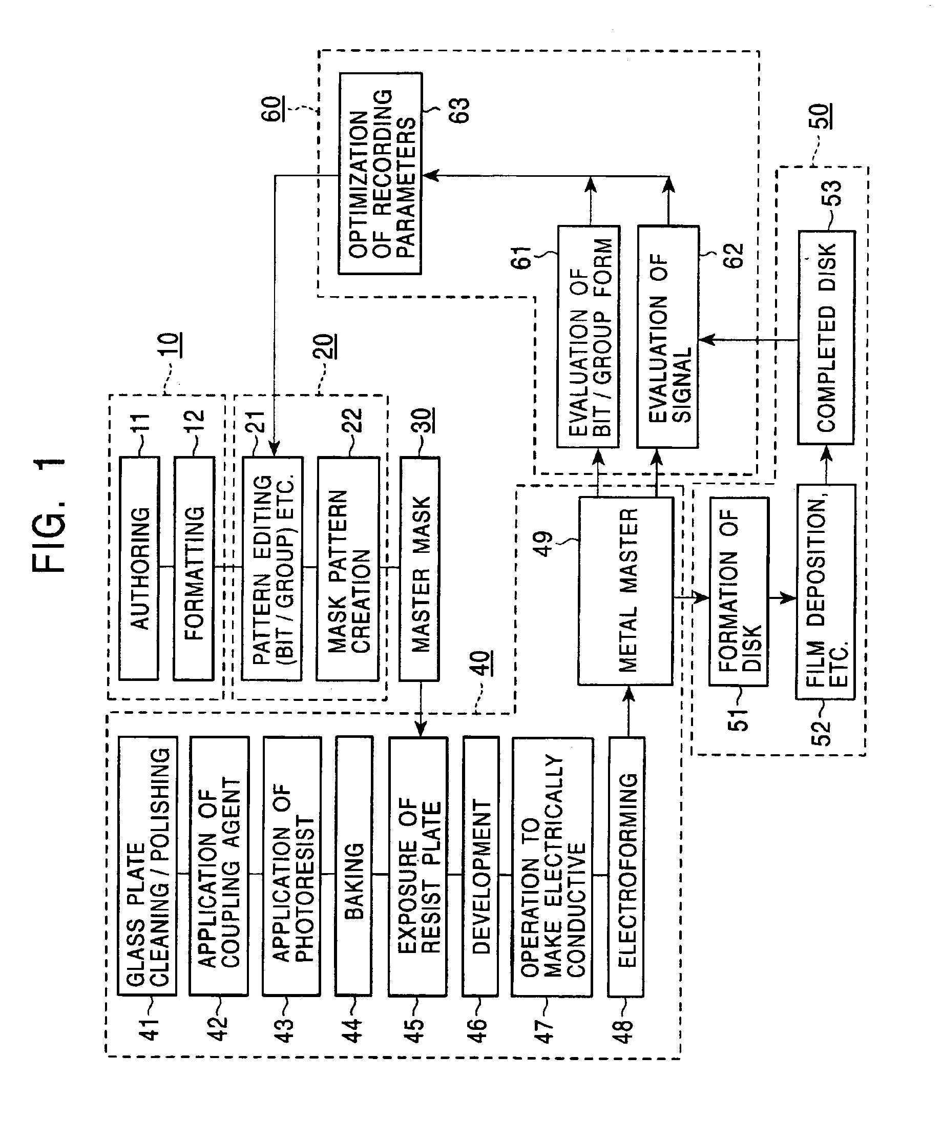
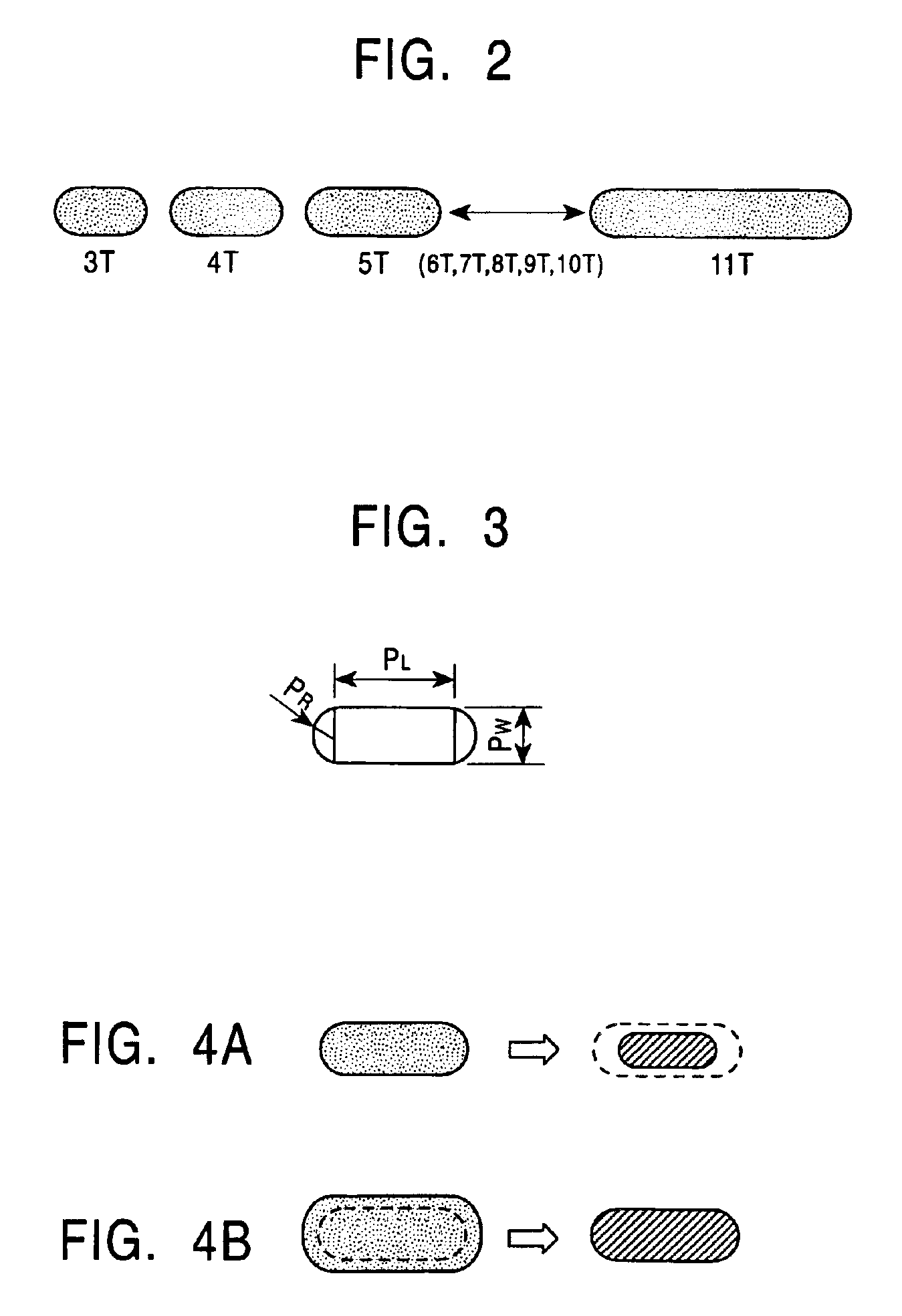
[0037]FIG. 1 illustrates the specific steps carried out in the method of producing an optical disk. In general, the method of producing an optical disk comprises a formatting step 10 for producing formatted data by formatting authoring data; a mask pattern generating step 20 for generating a mask pattern by making the formatted data obtained in the formatting step 10 correspond to basic pattern information obtained from basic signal pattern data required for various types of optical disks; a master mask forming step 30 for forming a master mask from the mask pattern generated in the mask pattern generating step 20; a metal master forming step 40 for forming a metal maste...


PUM


Abstract

A method of forming a mask pattern includes a formatting step for formatting authoring data in accordance with formats of specified media either by a fixed amount at a time or continuously. The authoring data is obtained by an authoring operation in which base information, such as image information or audio information, is edited. The method of forming a mask pattern also includes a mask pattern generating step in which basic pattern information is generated from basic signal pattern data necessary for various types of optical disks as a result of carrying out a pattern editing operation, and the basic pattern information is used to generate a mask pattern by carrying out a mask pattern generating operation. In the steps of a conventional method, it is necessary to carefully determine the conditions which allow disks produced after a plurality of later operations of the method have been carried out to satisfy standards. In addition, it is necessary to carefully observe at all times that these conditions are maintained during the long time required to produce the disks.

Description

BACKGROUND OF THE INVENTION[0001]1. Field of the Invention[0002]The present invention relates to a method of and device for forming a mask pattern used to form a master mask used in a projection / exposure step carried out to form a metal master serving as a master disk of an optical disk, and a method of producing an optical disk using the metal master formed in accordance with the mask pattern obtained using the method of and device for forming a mask pattern.[0003]2. Description of the Related Art[0004]A general description of the method of producing a master disk of an optical disk is given. The master disk of the optical disk is a metal master or a stamper, a die needed to form the optical disk, and a circular metallic plate which is approximately 0.3 mm thick and has a slightly convex surface for forming, for example, pits therein.[0005]Hereunder, a common method of producing a master disk of an optical disk is described with reference to FIG. 8.[0006]A glass plate is cleaned wi...

Claims


Application Information

Patent Timeline
IPC IPC(8): G11B20/12G11B7/0045G03F1/00G03F1/68G03F7/20G11B7/0055G11B7/26
CPCG11B7/261G03F7/2053G03F7/70383
Inventor HORI, KAZUHITO
Owner SONY CORP
Learn More