Microelectromechanical system

a micro-electromechanical and micro-electromechanical technology, applied in the direction of magnetic field micro-mechanical switches, electromagnetic relay details, etc., can solve the problems of large related art reed relays, inability to meet the needs of many applications, so as to achieve reliable and accurate operation.

Active Publication Date: 2012-05-08
STMICROELECTRONICS INT NV
View PDF3 Cites 7 Cited by
  • Summary
  • Abstract
  • Description
  • Claims
  • Application Information

AI Technical Summary

Benefits of technology

[0007]An advantage of the invention is to provide a MEMS switch that is formed in an integrated solid state MEMS technology.
[0008]Another advantage of the invention is to provide a MEMS switch formed on the micron or nanoscale that is very reliable and accurate in its operation.
[0009]Yet another advantage of the invention is to provide a MEMS switch with a cantilever architecture.
[0010]Still another advantage of the invention is to provide a MEMS switch with a torsion architecture.

Problems solved by technology

The related art reed relay is large, delicate and not reliable for many applications.
Such electronic switches are better alternatives to the reed relay switches, but they have a power consumption drawback.
That is, as more and more electronic circuit applications are battery operated, the benefits of an integrated switch having power consumption is problematic.

Method used


Image

  • Microelectromechanical system
  • Microelectromechanical system
  • Microelectromechanical system

Examples


Embodiment Construction

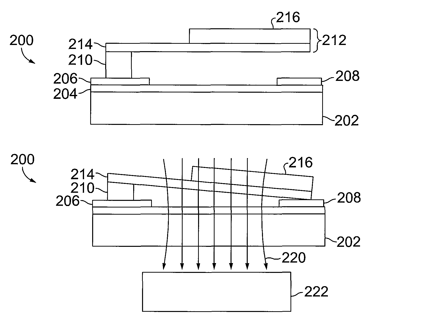
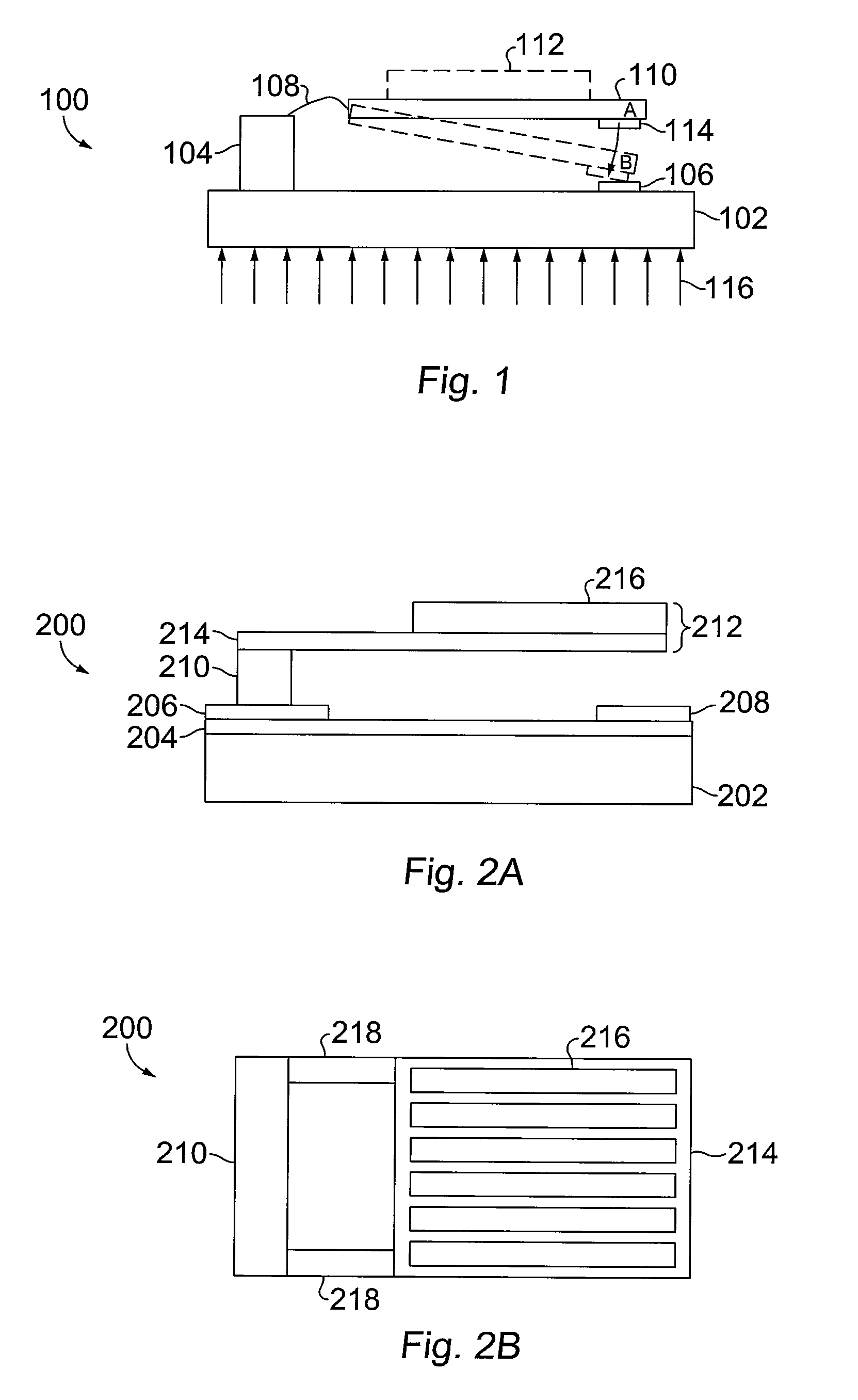
[0026]The invention relates to microelectromechanical systems, and more particularly, to MEMS switches using magnetic actuation. The MEMS switch may be actuated with no internal power consumption. That is, the switch may be actuated with an external magnetic field. The switch is formed in an integrated solid state MEMS technology. The MEMS switch is formed on the micron or nanoscale and very reliable and accurate. The MEMS switch can be designed into various architectures, e.g., a cantilever architecture and torsion architecture. The torsion architecture is more efficient than a cantilever architecture.

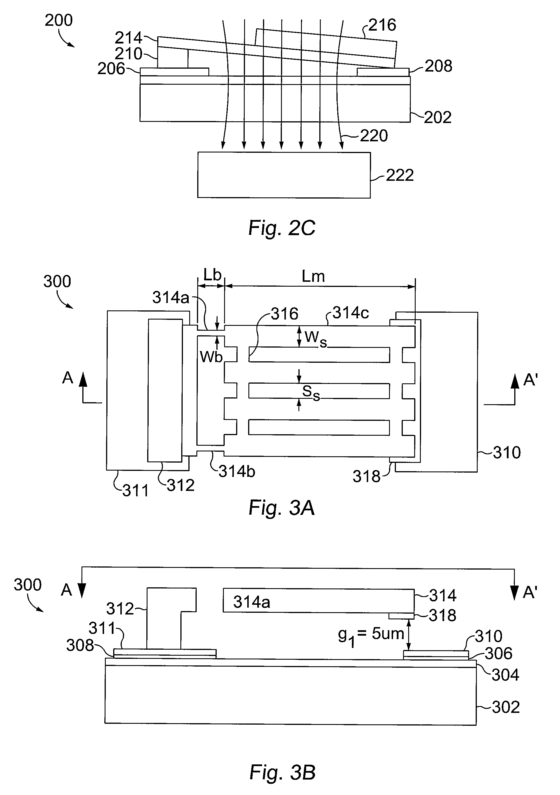
[0027]In one embodiment, a MEMS switch is formed on a substrate. The substrate may be a silicon on insulator (SOI) substrate, glass substrate, silicon (Si) substrate, plastic substrate, and the like. Other substrates may also be used.

[0028]The substrate may include insulating material. The insulating material may be formed into a thin insulator layer. The insulating material may be a ...


PUM


Abstract

The invention relates to microelectromechanical systems (MEMS), and more particularly, to MEMS switches using magnetic actuation. The MEMS switch may be actuated with no internal power consumption. The switch is formed in an integrated solid state MEMS technology. The MEMS switch is micron and / or nanoscale, very reliable and accurate. The MEMS switch can be designed into various architectures, e.g., a cantilever architecture and torsion architecture. The torsion architecture is more efficient than a cantilever architecture.

Description

[0001]This application claims the benefit of U.S. Provisional Patent Application No. 61 / 142,572, filed on Jan. 5, 2009, which is hereby incorporated by reference for all purposes as if fully set forth herein.BACKGROUND OF THE INVENTION[0002]1. Field of the Invention[0003]The invention relates to microelectromechanical systems (MEMS), and more particularly, to MEMS switches using magnetic actuation.[0004]2. Discussion of the Related Art[0005]Some related art electrical switches are controlled with an electrical circuit such as a reed relay. A reed relay is an electrical switch and is a very common electronic component widely used in many applications. Typically, a reed relay includes a glass package having two metal contacts. The metal contacts may be actuated with a magnetic field. The related art reed relay is large, delicate and not reliable for many applications. Some other related art electronic switches are based on magnetic effect like the Hall effect or giant magneto resistan...

Claims


Application Information

Patent Timeline
Patent Type & Authority Patents(United States)
IPC IPC(8): H01P1/10H01H55/00
CPCH01H50/005H01H2036/0093
Inventor MIN, TANGEBIN, LIAONOVIELLO, GIUSEPPEITALIA, FRANCESCO
Owner STMICROELECTRONICS INT NV
Why Eureka
Try Eureka