Eureka AIR delivers breakthrough ideas for toughest innovation challenges, trusted by R&D personnel around the world.

Bow energy transfer system and method

Active Publication Date: 2014-02-25
PRECISION SHOOTING EQUIP
View PDF13 Cites 4 Cited by
  • Summary
  • Abstract
  • Description
  • Claims
  • Application Information

AI Technical Summary

Benefits of technology

The present invention is about adding extra mass to the bowstring of a bow to make it more efficient in transferring energy to the arrow or bolt. This is done by using helical springs made of metal that are positioned on the bowstring. These springs completely encircle the bowstring and cannot be dislodged during the bow discharge, regardless of the violent energy transfer. The flexing of the springs during bowstring travel increases the efficiency and speed of the bolt or arrow. The helical springs are secured in position on the bowstring by using serving wound between individual coils of the spring. This results in a force exerted by the spring on the bowstring to lock it securely in position.

Problems solved by technology

The smooth and efficient delivery of the potential energy stored in the flexed limbs to the arrow, to produce kinetic energy in the form of motion of the arrow, is difficult to achieve and usually results in residual energy remaining in the bow system after the arrow's departure that is dissipated in the form of vibration, noise, and in some instances can result in the generation of a bowstring shockwave propagating along the bowstring to the cams of the system causing the bowstring to derail and jump off the cam track.
That is, the high forces being transmitted to the bowstring during bowstring release may result in the propagation of a standing wave along the length of the bowstring resulting in the bowstring derailing from the groove of the cam or wheel.
These difficulties are particularly acute with crossbows.
In high powered compound bows, and particularly with crossbows, the violence accompanying the release of the bowstring and the transfer of energy from the limbs to the arrow may result in forces acting upon the weights that cause them to move along the length of bowstring and thus change their position (and the characteristics and effect of the added mass) and in some instances may even be dislodged from the bowstring resulting in a dangerous condition wherein the dislodged weight, traveling at a high rate of speed, may strike the archer or a spectator.
These polymer weights grasp the bowstring through the elasticity of the polymer; however, the violence of the release of the bowstring temporarily and radically deforms these polymer weights resulting in the loss of precise positioning of the weight and in some cases destruction of the weight.
Further, it is difficult to achieve sufficient mass through the utilization of polymer weights.

Method used


Image

  • Bow energy transfer system and method
  • Bow energy transfer system and method
  • Bow energy transfer system and method

Examples


Embodiment Construction

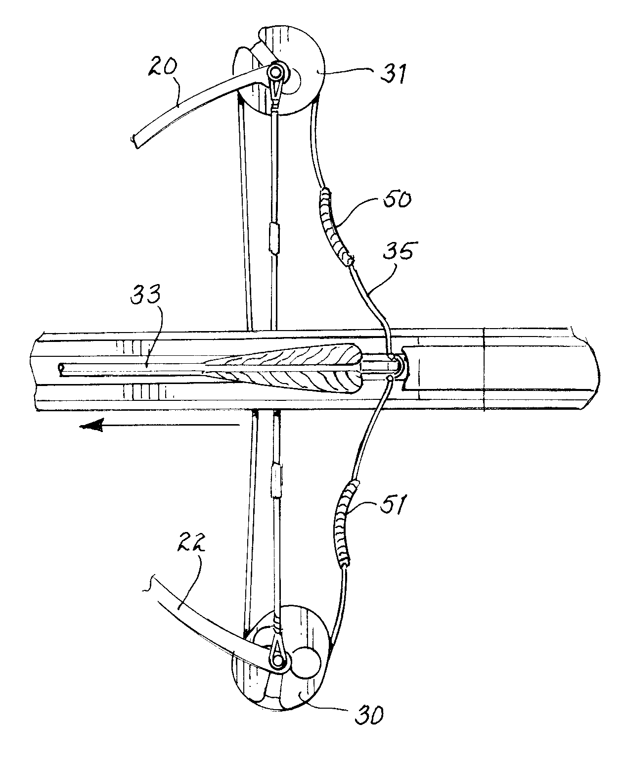
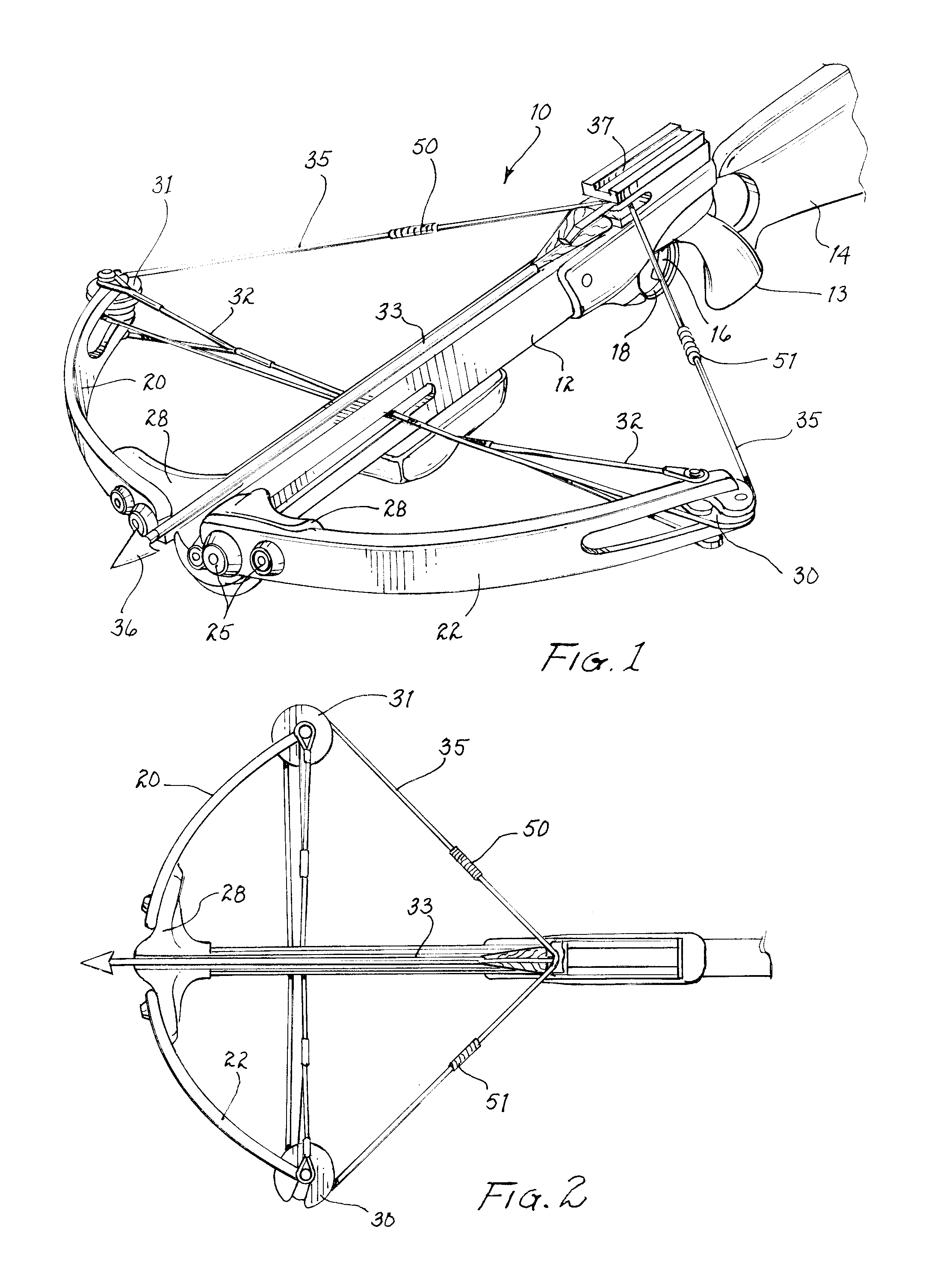
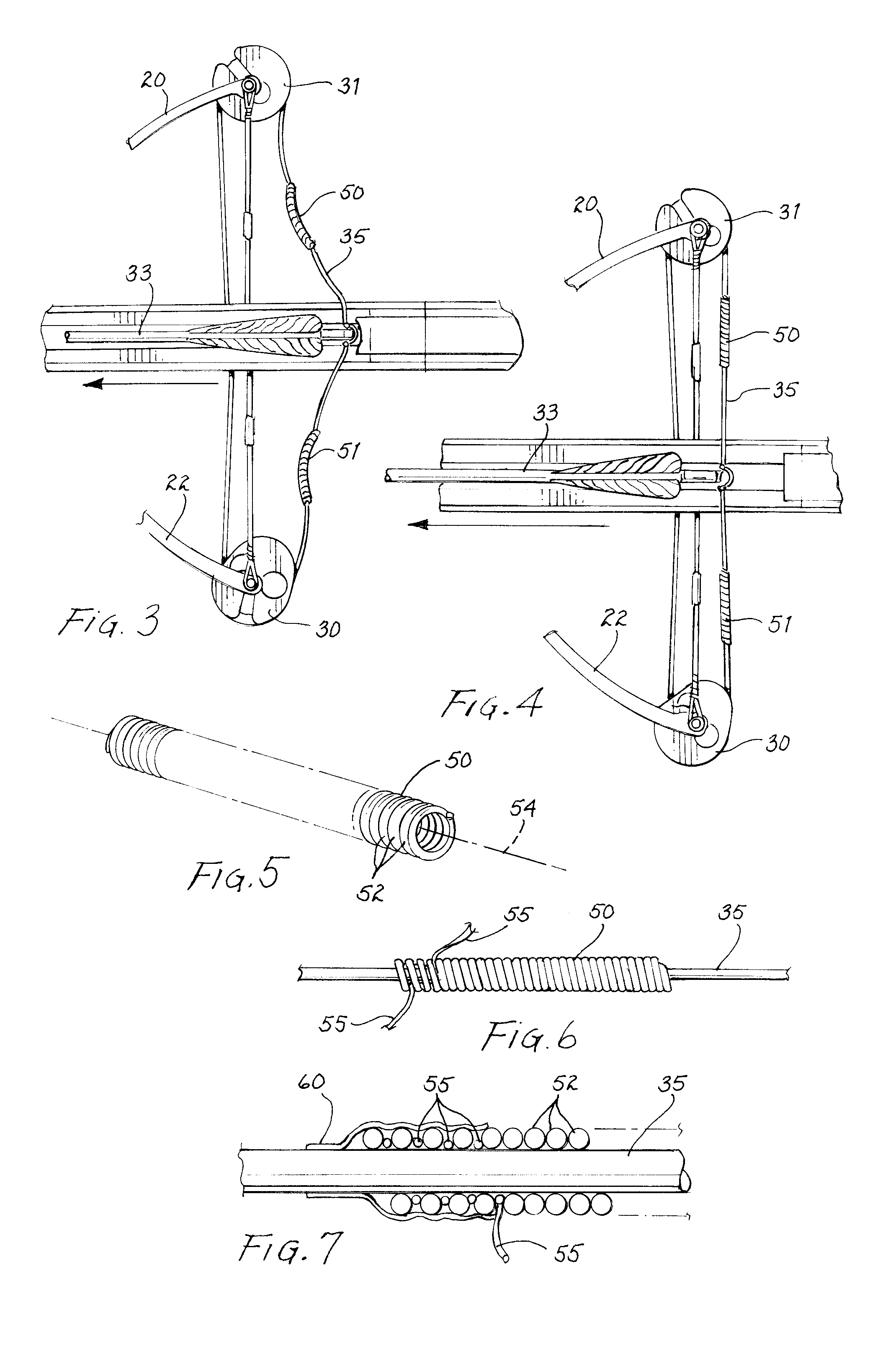
[0014]Referring to FIGS. 1 and 2, an archery bow 10 constructed in accordance with the teachings of the present invention is shown. The archery bow system shown in FIGS. 1 and 2 is a crossbow; however, the present invention is equally applicable to compound bows, and particularly to bows, crossbows or compound bows, that have a high draw weight. The crossbow is provided with a stock forearm 12 that includes a grip 13 and a stock butt 14. A trigger 16 and a trigger guard 18 are provided to permit the crossbow to be discharged. The crossbow system includes limbs 20 and 22 secured by limb bolts 25 to a riser 28 which in turn is secured to the stock 12. As used herein, the term riser includes other terms that may be used for the support used for mounting the limbs; in crossbow terminology, the riser is sometimes referred to as a retainer, a prod, or a mounting bracket. The limbs each support a cam 30 or a wheel 31 and provide anchor points for cables 32 extending from the cam or wheel t...


PUM


Abstract

A bow energy transfer system includes a pair of helically wound springs positioned on the bowstrings on either side of the bowstring nock point; the springs are secured to the bowstring with a serving thread wound between the individual coils into contact with the bowstring. The springs flex perpendicular to their longitudinal axes during discharge of the bow causing energy to temporarily be stored in the flexed spring to be returned to the arrow or bolt later in its discharge.

Description

FIELD OF THE INVENTION[0001]The present invention pertains to archery bows and systems, and particularly to systems having a high draw weight wherein the transfer of energy from flexed limbs to an arrow or bolt may be enhanced by the addition of mass to the bowstring.BACKGROUND OF THE INVENTION[0002]High powered archery bows, that is, bows and crossbows with high draw weight, must efficiently deliver the substantial stored energy in flexed limbs through the bowstring to the arrow or bolt. The smooth and efficient delivery of the potential energy stored in the flexed limbs to the arrow, to produce kinetic energy in the form of motion of the arrow, is difficult to achieve and usually results in residual energy remaining in the bow system after the arrow's departure that is dissipated in the form of vibration, noise, and in some instances can result in the generation of a bowstring shockwave propagating along the bowstring to the cams of the system causing the bowstring to derail and j...

Claims


Application Information

Patent Timeline
IPC IPC(8): F41B5/00
CPCF41B5/00F41B5/10F41B5/123F41B5/1411
Inventor KRONENGOLD, DAVID H.RASOR, JR., ALLEN C.HANSEN, KEVIN L.GRIMES, RONALD C.LISKA, JR., JOHN M.
Owner PRECISION SHOOTING EQUIP
Why Eureka
Eureka Blog
Learn More