High accuracy sin-cos wave and frequency generators, and related systems and methods

a frequency generator and high-accuracy technology, applied in oscillator generators, trigometric functions, instruments, etc., can solve the problems of high accuracy decay rate of recursive calculation stability, increase in hardware cost, and increase in complexity of calculations, so as to achieve high accuracy and low hardware cost. , the effect of high accuracy

Inactive Publication Date: 2014-02-25
QUALCOMM INC
View PDF25 Cites 1 Cited by
  • Summary
  • Abstract
  • Description
  • Claims
  • Application Information

AI Technical Summary

Benefits of technology

[0008]Embodiments disclosed in the detailed description include high accuracy sine and / or cosine (sin-cos) wave and frequency generators, and related systems and methods. In non-limiting embodiments disclosed herein, the sin-cos wave generators can provide highly accurate sin-cos values for sin-cos wave generation with low hardware cost and small lookup table requirements. The embodiments disclosed herein may include a circuit to conduct an arithmetic approximation of a sin-cos curve based on a phase input. The circuit may be in communication with a point lookup table and a correction lookup table. The tables may receive the phase input and match the phase input to main sin-cos endpoints associated with the phase and to a correction value for the phase. These values which are selected based on the phase input, may be communicated to a converter circuit where the arithmetic functions are applied to the values resulting in a sin-cos curve value.
[0009]In this regard in one embodiment, a frequency generator is provided. The frequency generator includes a phase accumulator configured to generate a phase signal representing a phase angle. A sin-cos converter in communication with the phase accumulator receives the phase signal as a phase input. The sin-cos converter generates a sin-cos curve value as a converter output. The sin-cos curve value is approximately equal to a sin-cos value at the phase angle within a predefined tolerance. The sin-cos converter further includes a point lookup table having main sin-cos endpoints at predefined intervals in a first angle range. Each of the main sin-cos endpoints comprise the sin-cos curve value at a given angle among the intervals. The sin-cos converter also includes a correction lookup table having a plurality of correction values representing a difference between sub-main sin-cos endpoints at intervals in a second angle range between two associated main sin-cos endpoints in the point lookup table, and approximations of the sin-cos curve values at given angles among the intervals. A point selection circuit of the sin-cos converter provides a first main sin-cos endpoint associated with a first side of the phase angle, and a second main sin-cos endpoint associated with a second side of the phase angle from the point lookup table. A correction selection circuit of the sin-cos converter provides a first correction value correlated with the first main sin-cos endpoint and a second correction value correlated with the second main sin-cos endpoint from the correction lookup table. A converter circuit of the sin-cos converter provides the sin-cos curve value at the phase angle in a converter output signal based on the first and second main sin-cos endpoints and the first and second correction values. In this manner, the correction values can be calculated from main sin-cos endpoints which can be repeatedly applied for phase angles having the same correction values without having to store large numbers of sin-cos values for an entire unit circle.
[0012]In another embodiment, a computer-readable medium is provided. The computer-readable medium has stored thereon computer-executable instructions to cause a frequency generator to generate a phase signal representing a phase angle, and receive the phase signal as a phase input. The computer-executable instructions further cause the frequency generator to receive from a point lookup table, which comprises main sin-cos endpoints at predefined intervals in a first angle range, each of the main sin-cos endpoints comprising a sin-cos curve value at a given angle among the intervals, a first main sin-cos endpoint associated with a first side of the phase angle and a second main sin-cos endpoint associated with a second side of the phase angle. The computer-executable instructions further cause the frequency generator to receive from a correction lookup table, which comprises correction values representing a difference between the first sub-main sin-cos endpoints at intervals in a second angle range between two associated main sin-cos endpoints in the point lookup table and approximations of the sin-cos curve values at given angles among the intervals, a first correction value correlated with the first main sin-cos endpoint and a second correction value correlated with the second main sin-cos endpoint. The computer-executable instructions further cause the frequency generator to generate the sin-cos curve value as a converter output, the sin-cos curve value approximately equal to a sin-cos value at the phase angle within a predefined tolerance based on the first and second main sin-cos endpoints and the first and second correction values.

Problems solved by technology

However, hardware cost is increased, because more tables are needed and polynomial equations increase the complexity of the calculations.
Infinite Impulse Response (IIR) filters can produce sin waves, but the stability of the recursive calculation has a high rate of precision decay, even if only required for a short number of cycles.
With any of the existing methods of approximating a sin-cos wave, there is a tradeoff between accuracy, cost, and efficiency.
This can result in higher hardware costs based on the amount and complexity of the required hardware, and increased demands for processing time and power.

Method used


Image

  • High accuracy sin-cos wave and frequency generators, and related systems and methods
  • High accuracy sin-cos wave and frequency generators, and related systems and methods
  • High accuracy sin-cos wave and frequency generators, and related systems and methods

Examples


Embodiment Construction

[0020]With reference now to the drawing figures, several exemplary embodiments of the present disclosure are described. The word “exemplary” is used herein to mean “serving as an example, instance, or illustration.” Any embodiment described herein as “exemplary” is not necessarily to be construed as preferred or advantageous over other embodiments.

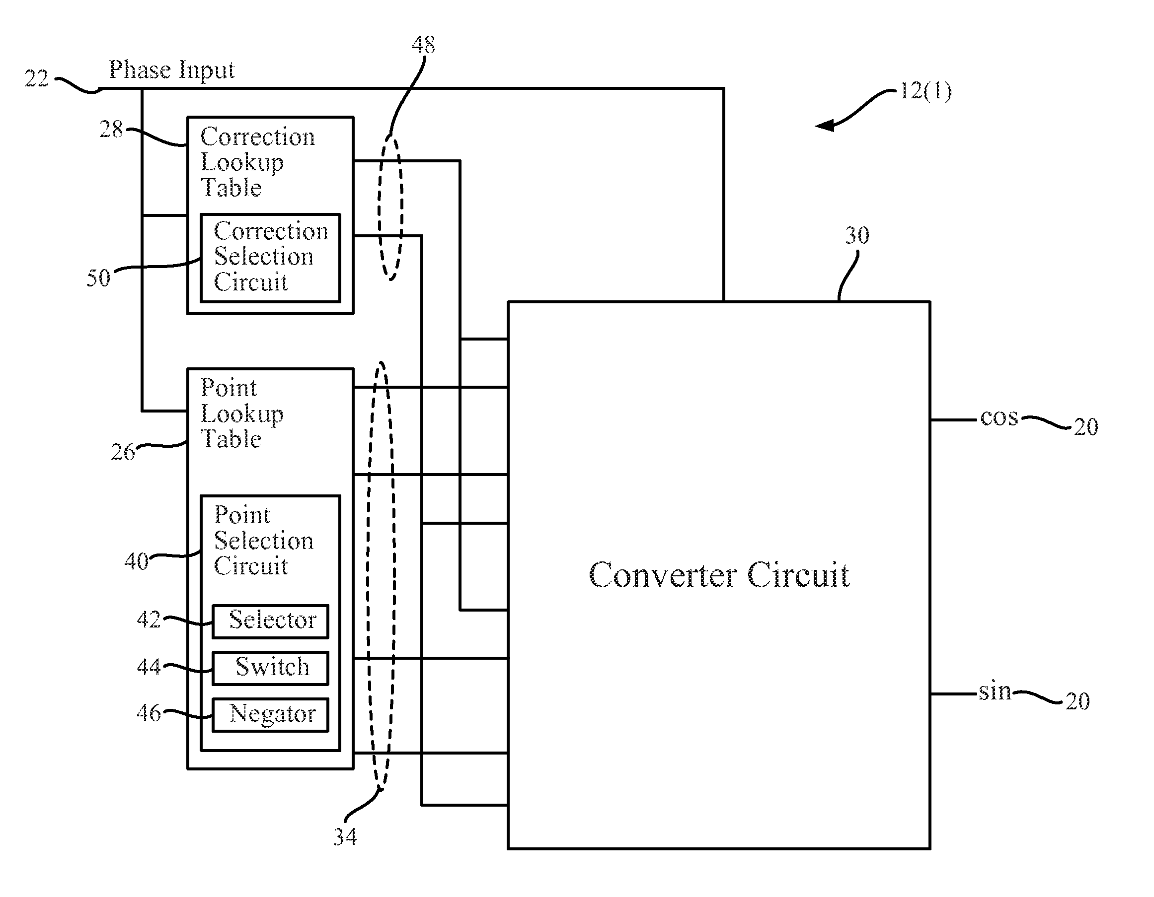
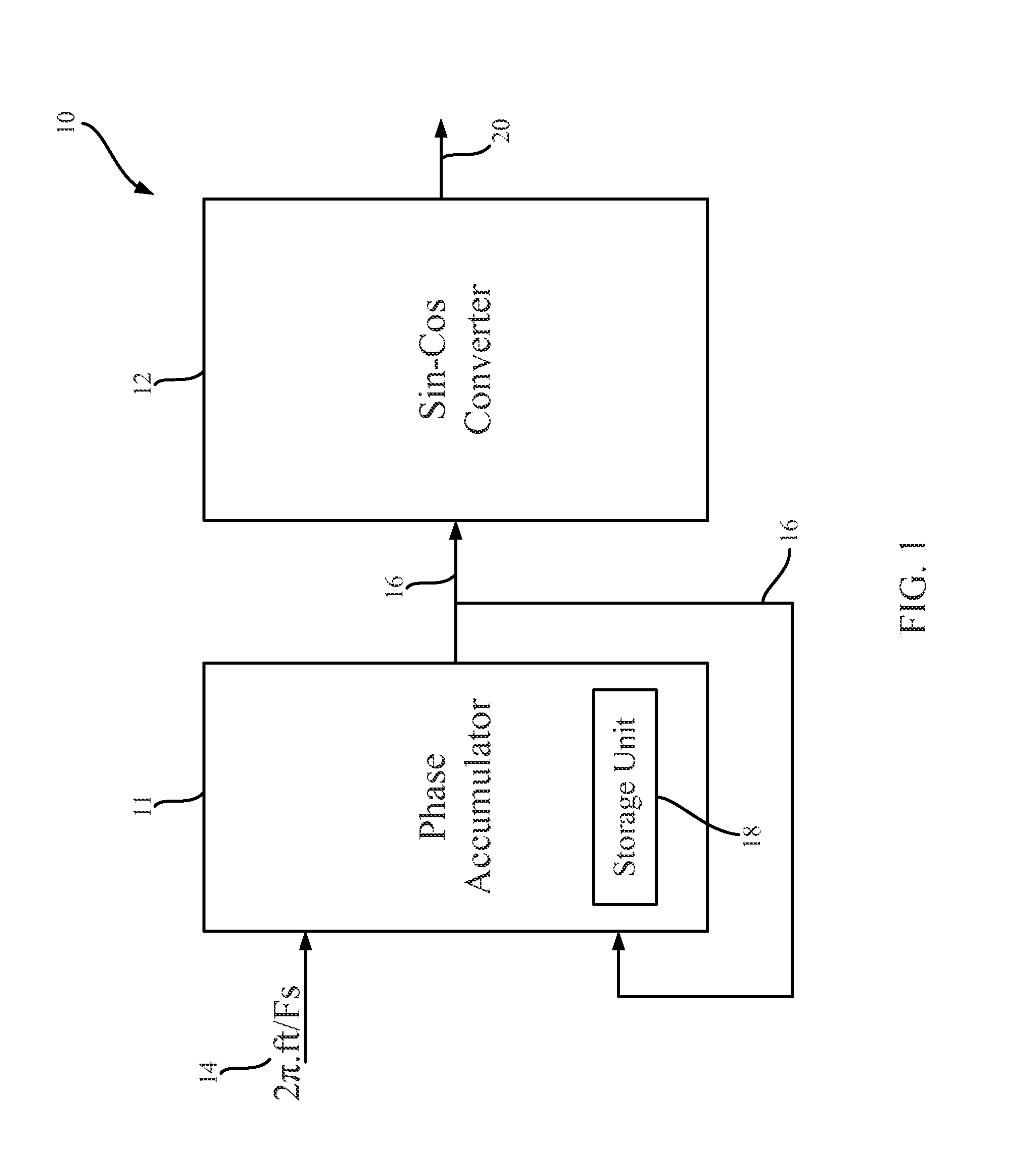
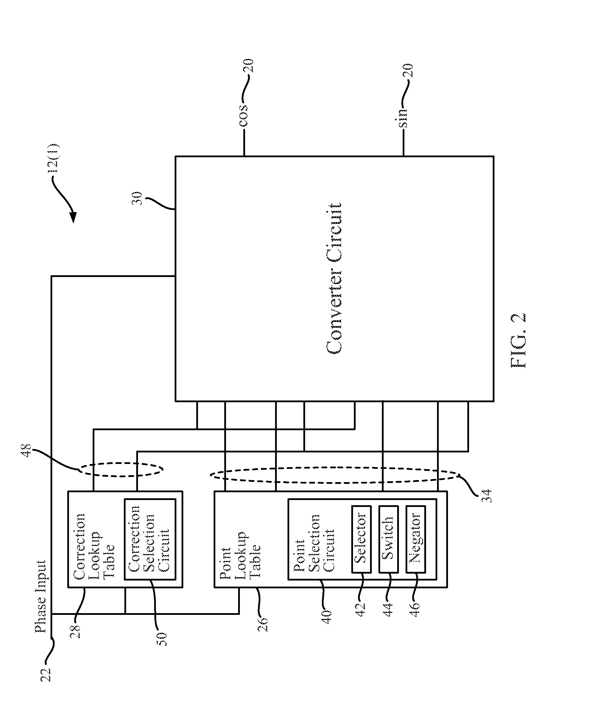
[0021]Embodiments disclosed in the detailed description include high accuracy sine and / or cosine (sin-cos) wave and frequency generators, and related systems and methods. In non-limiting embodiments disclosed herein, the sin-cos wave generators can provide highly accurate sin-cos values for sin-cos wave generation with low hardware cost and small lookup table requirements. The embodiments disclosed herein may include a circuit to conduct an arithmetic approximation of a sin-cos curve based on a phase input. The circuit may be in communication with a point lookup table and a correction lookup table. The tables may receive the phase input an...


PUM


Abstract

High accuracy sin-cos wave and frequency generators, and related systems and methods. In non-limiting embodiments disclosed herein, the sin-cos wave generators can provide highly accurate sin-cos values for sin-cos wave generation with low hardware costs and small lookup table requirements. The embodiments disclosed herein may include a circuit to conduct an arithmetic approximation of a sin-cos curve based on a phase input. The circuit may be in communication with a point lookup table and a correction lookup table. The tables may receive the phase input and match the phase input to main sin-cos endpoints associated with the phase, and to a correction value for the phase. These values which are selected based on the phase input, may be communicated to a converter circuit where the arithmetic functions are applied to the values resulting in a sin-cos curve value.

Description

PRIORITY APPLICATION[0001]The present application claims priority to U.S. Provisional Patent Application Ser. No. 61 / 587,689 entitled “HIGH ACCURACY SIN-COS WAVE AND FREQUENCY GENERATORS, AND RELATED SYSTEMS AND METHODS” filed on Jan. 18, 2012, which is hereby incorporated herein by reference in its entirety.BACKGROUND[0002]I. Field of the Disclosure[0003]The technology of the disclosure relates to frequency generators that gauge frequency signals based on sine and cosine values.[0004]II. Background[0005]It is common in numerous industries to use various methods to approximate sine (sin) and / or cosine (cos) (sin-cos) wave signals from an existing or generated input signal. Such signal approximation is used for data and voice communications, including audio and visual communications in the telecommunications and entertainment industries. Other uses may include providing signals for testing equipment for development and manufacturing of electronic components, or for troubleshooting de...

Claims


Application Information

Patent Timeline
Patent Type & Authority Patents(United States)
IPC IPC(8): H03B28/00
CPCG06F1/0356G06F1/0353G06F2101/04G06F1/0342
Inventor HOYLE, DAVID, J.
Owner QUALCOMM INC
Why Eureka
Try Eureka