Multibit magnetic random access memory cell with improved read margin
a multi-bit magnetic random access and memory cell technology, applied in read-only memories, instruments, static storage, etc., can solve the problem of large currents for writing and reading information, and achieve the effect of improving the read margin
- Summary
- Abstract
- Description
- Claims
- Application Information
AI Technical Summary
Benefits of technology
Problems solved by technology
Method used
Image
Examples
example 1
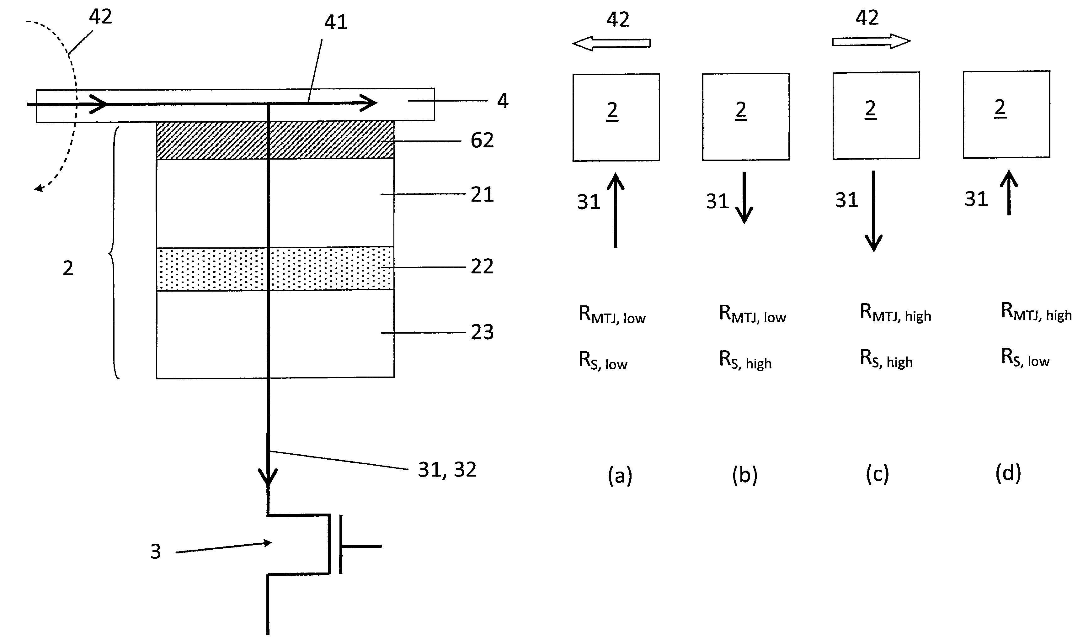
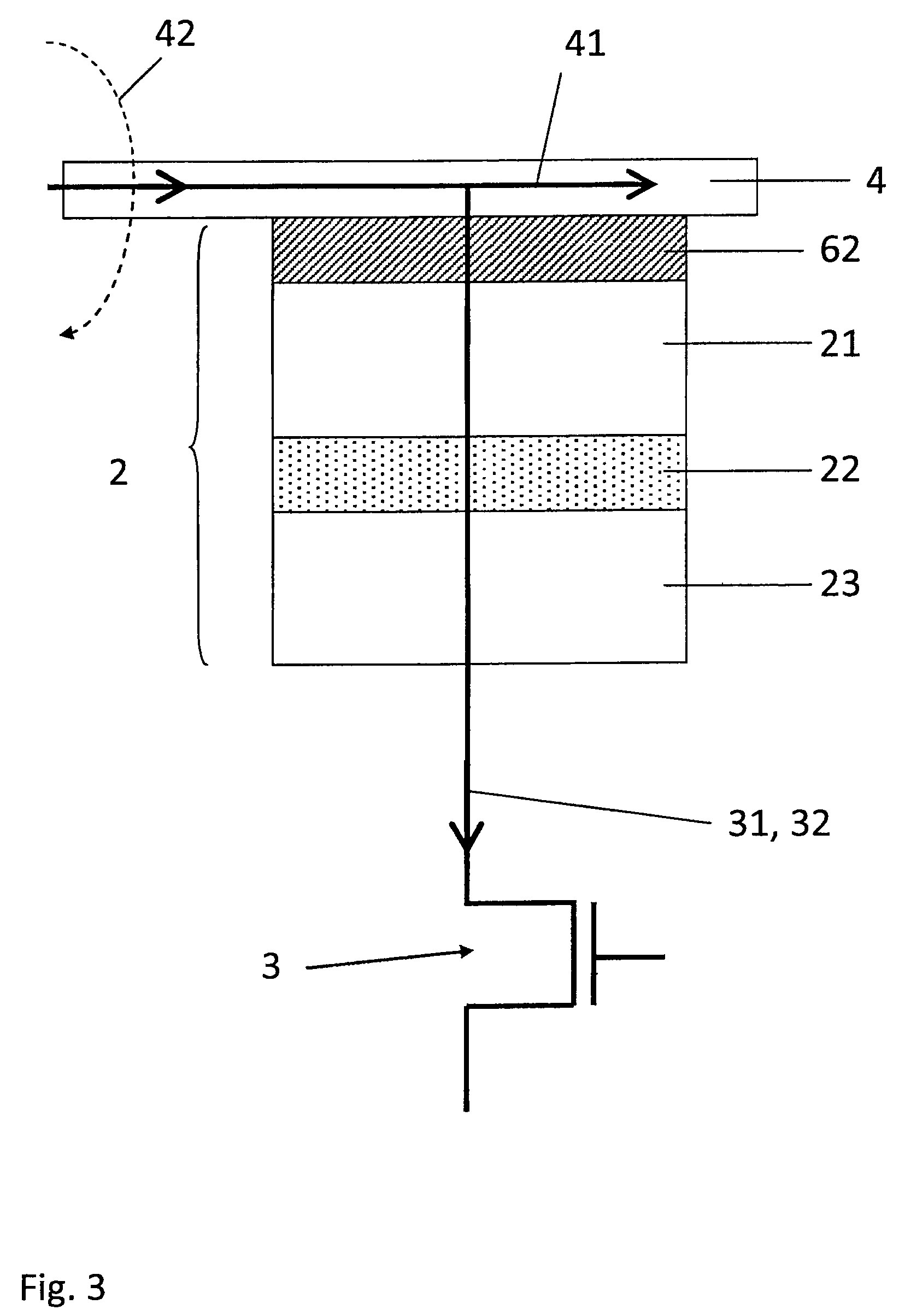
[0050]A write operation of the MRAM cell 1 is represented schematically in FIG. 4 according to an embodiment. The thermally assisted write operation comprises heating the magnetic tunnel junction 2 and varying the junction resistance RMTJ by passing the first field current 41 in the first current line 4 such as to generate the first magnetic field 42. The switching resistance RS is switched according to the polarity of the switching current 31 passing in the magnetic tunnel junction 2, for instance, in the case of the switching resistant element 62 having a bipolar resistance switching behavior. Here, the switching current 31 can also be used as the heating current. In the present embodiment, it is assumed that the switching resistance RS can be switched when the switching current 31 is passed with a first switching magnitude that is lower than a heating magnitude of the switching current 31, required for heating the magnetic tunnel junction at the high temperature threshold.
[0051]M...
example 2
[0055]FIG. 5 illustrates the thermally assisted write operation of the MRAM cell 1 according to another embodiment. In this embodiment, it is assumed that the switching resistance RS is switched according to the magnitude of the switching current 31, for instance, in the case of the switching resistant element 62 having a unipolar resistance switching behavior. More particularly, it is assumed that the switching resistance RS is switched to the low switching resistance level RS, low when the switching current 31 is passed with the first switching magnitude, and switched to the high switching resistance level RS, high when the switching current 31 is passed with a second switching magnitude, higher that the first switching magnitude. It is further assumed that the first and second switching magnitudes are lower that the heating magnitude.
[0056]In step (a) of FIG. 5, the first field current 41 is passed in the first current line 4 such as to generate the first magnetic field 42 in a d...
example 3
[0058]In yet another embodiment illustrated in FIG. 6, the thermally assisted write operation of the MRAM cell 1 comprises varying the junction resistance RMTJ by having the switching current 31 passed in the magnetic tunnel junction 2 being spin polarized. The spin polarized switching current 31 induces a local spin torque on the second magnetic layer 23 adjusting its magnetization direction according to the polarity of the spin polarized current. The spin polarized current must be passed at the heating magnitude such that the magnetic tunnel junction 2 is heated at the high temperature threshold. In this embodiment, it is assumed that the switching resistant element 62 has a bipolar resistance switching behavior and that the heating magnitude is lower than the first switching magnitude.
[0059]More particularly, in step illustrated in FIG. 6 (a), the switching current 31 is passed at the first switching magnitude such as to switch the switching resistance RS, for example to the low ...
PUM
 Abstract
Description
Claims
Application Information
 - R&D
- Intellectual Property
- Life Sciences
- Materials
- Tech Scout
- Unparalleled Data Quality
- Higher Quality Content
- 60% Fewer Hallucinations
Browse by: Latest US Patents, China's latest patents, Technical Efficacy Thesaurus, Application Domain, Technology Topic, Popular Technical Reports.
© 2025 PatSnap. All rights reserved.Legal|Privacy policy|Modern Slavery Act Transparency Statement|Sitemap|About US| Contact US: help@patsnap.com


