Heat exchanger having swirling means

a technology of heat exchanger and spherical means, which is applied in the field of heat exchanger, can solve the problems of large amount of ice arriving at the engine, fuel system malfunction, and fine clearance valve malfunctioning,

Active Publication Date: 2014-03-04
ROLLS ROYCE PLC
View PDF14 Cites 9 Cited by
  • Summary
  • Abstract
  • Description
  • Claims
  • Application Information

AI Technical Summary

Benefits of technology

[0013]At its broadest, a first aspect of the present invention provides a heat exchanger in which the fuel entering the heat exchanger is caused to swirl in order to separate any entrained ice. This allows different parts of the heat exchanger to be adapted to deal with the ice whilst fuel with low or zero concentrations of ice continues to pass through the heat exchanger to downstream components.
[0019]In another embodiment the swirl inducing means includes a guide vane arranged to cause the fuel to swirl prior to the fuel entering said matrix. The swirl inducing means may include a plurality of such guide vanes. Guide vanes may be used to cause fuel which enters a heat exchanger in standard fashion to swirl. A plurality of guide vanes may be used to improve the uniformity of the swirled fuel flow.
[0021]A driven element as part of the swirl inducing means can ensure that a sufficient velocity of swirling fuel flow is achieved in the heat exchanger, and in particular that the velocity of the swirling fuel flow is not affected by the rate of fuel flow entering the heat exchanger.
[0024]A gas turbine engine according to this aspect provides for improved resistance to icing in the fuel input to the engine and therefore improved safety in operation and a wider operating range for the engine. The provision of a heat exchanger according to the above first aspect may mean that the ice tolerance of the fuel supply system of the engine downstream of the heat exchanger can be reduced due to the improved ice treatment carried out in the heat exchanger.
[0028]The step of causing the fuel to swirl may cause at least some of the entrained ice to deposit on a surface of the heat exchanger prior to the fuel entering the heat exchanger matrix. This ice may therefore be prevented from entering the heat exchange matrix and blocking it.

Problems solved by technology

These ice particles present a problem for the fuel system in that they can block small passages and cause fine clearance valves to malfunction.
However, if there is ice accumulation in the fuel pipe work supplying the engine, this ice accumulation can break away or “shed” and result in a large quantity of ice arriving at the engine over a short period of time.
Such quantities of ice can overwhelm and block the fuel-oil heat exchanger and as a result interrupt the fuel supply causing the fuel system to malfunction and the engine to loose power.
In many cases, these components (in particular units such as filters) will only have a finite capability to deal with the ice content of the fuel.
Another problem with this arrangement is that it relies on the transiently high level of ice in the fuel to occur over a short period of time, such that all of this ice is captured in the heat exchanger inlet before the bypass is opened, otherwise fuel could be delivered to the downstream components which still contains high concentrations of ice which would cause malfunction of those components.

Method used


Image

  • Heat exchanger having swirling means
  • Heat exchanger having swirling means
  • Heat exchanger having swirling means

Examples


first embodiment

[0040]FIGS. 3a and 3b show a heat exchanger 30 according to the present invention. As shown in the external view of FIG. 3b, heat exchanger 30 is substantially cylindrical in overall form and has a fuel inlet 32 located at one end of the heat exchanger.

[0041]FIG. 3a shows a cross section through the central plane of the heat exchanger 30. The direction of fuel movement through the heat exchanger is shown by arrows F. Walls 36 enclose the components of the heat exchanger. In the interior of the heat exchanger 30 there is a fuel inlet cavity 34 and a heat-exchanger matrix 35. The heat exchanger matrix 35 may be in any known form, but in this embodiment comprises a plurality of tubes 40 and a plurality of passages 38 around the tubes. The tubes 40 allow fuel to pass from the fuel inlet cavity through the heat-exchanger whilst hot oil from the engine is passed around the outside of the tubes 40 through the passages 38 so as to warm the fuel passing through tubes 40.

[0042]The fuel inlet ...

second embodiment

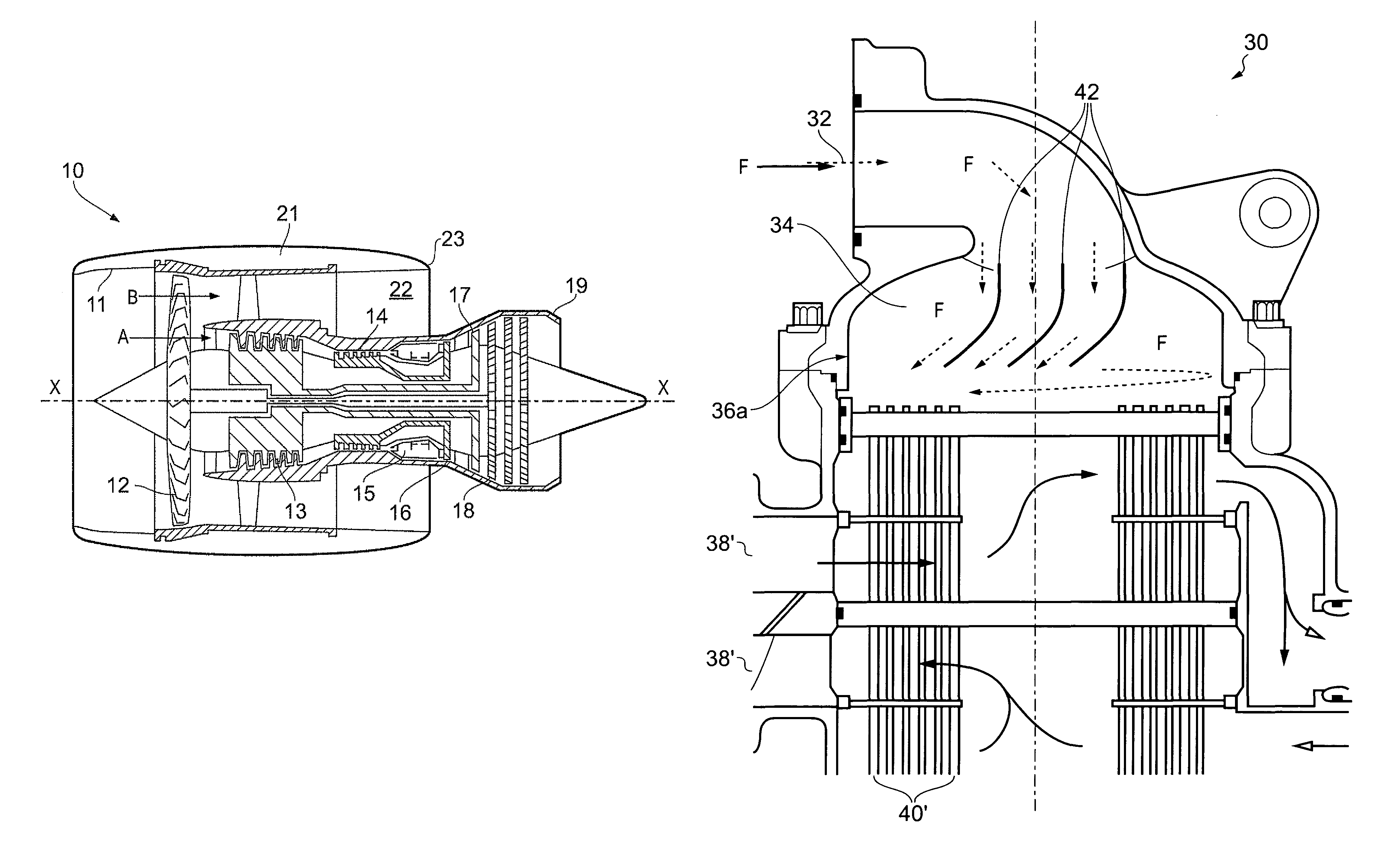
[0047]FIG. 4 shows a heat exchanger 30 according to the present invention. In this embodiment, fuel inlet 32 is arranged to deliver the fuel centrally to the fuel inlet cavity 34. Arranged within the fuel inlet cavity 34 are a plurality of guide vanes 42 which deflect the fuel entering the cavity and are arranged so as to cause the fuel to swirl within the fuel inlet cavity as shown by the flow arrows F.

[0048]Again the swirl induced in the fuel entering the heat exchanger 30 causes any entrained ice particles to concentrate in the outer region of the fuel in the fuel inlet cavity 34 and be deposited on the outer wall of the heat exchanger in the region 36a or on the face of the heat exchanger matrix 35 in the outer region of the heat exchanger, thereby continuing to allow fuel to flow through the more central regions of the heat exchanger matrix 35.

[0049]In the embodiment shown in FIG. 4, a different arrangement of heat exchanger matrix 35 is provided. In this arrangement the fuel p...


PUM


Abstract

A heat exchanger is provided for warming fuel prior to introduction of the fuel to an engine, the heat exchanger including: a fuel inlet and a fuel outlet; a heat exchange matrix having heat transfer components past which the fuel flows between said inlet and said outlet and which are arranged to be heated; and swirl inducing means arranged between said inlet and said matrix arranged to cause fuel from said inlet to swirl prior to entering said matrix. By causing the fuel to swirl prior to entering the heat exchange matrix, entrained ice in the fuel can be caused to concentrate at an outer region of the heat exchanger thereby allowing fuel to continue to flow through the heat exchanger to the engine even when ice is present in the fuel.

Description

FIELD OF THE INVENTION[0001]The present invention relates to a heat exchanger and a method of operating a heat exchanger. The invention is particularly, but not exclusively, concerned with a heat exchanger which pre-heats fuel being supplied to a gas turbine and in which the effects of fuel borne ice can be reduced.BACKGROUND OF THE INVENTION[0002]With reference to FIG. 1, a ducted fan gas turbine engine generally indicated at 10 has a principal and rotational axis X-X. The engine comprises, in axial flow series, an air intake 11, a propulsive fan 12, an intermediate pressure compressor 13, a high-pressure compressor 14, combustion equipment 15, a high-pressure turbine 16, and intermediate pressure turbine 17, a low-pressure turbine 18 and a core engine exhaust nozzle 19. A nacelle 21 generally surrounds the engine 10 and defines the intake 11, a bypass duct 22 and a bypass exhaust nozzle 23.[0003]The gas turbine engine 10 works in a conventional manner so that air entering the inta...

Claims


Application Information

Patent Timeline
Patent Type & Authority Patents(United States)
IPC IPC(8): F02K99/00
CPCF28F13/125F28D7/1669F28F27/02F28F9/0268F28F13/12F28F9/026F02C7/224
Inventor FOSTER, PETER, F, W
Owner ROLLS ROYCE PLC
Why Eureka
Try Eureka