Proportional pressure control valve

a technology of proportional pressure control and valve body, which is applied in the direction of fluid pressure control, process and machine control, instruments, etc., can solve the problems of considerable installation length and comparatively complex construction, and achieve the effect of simple and compact construction

Active Publication Date: 2014-03-04
HYDAC FLUITECHNIK GMBH
View PDF14 Cites 18 Cited by
  • Summary
  • Abstract
  • Description
  • Claims
  • Application Information

AI Technical Summary

Benefits of technology

[0004]An object of the invention is to provide an improved proportional pressure control valve which can be set, accordin...

Problems solved by technology

For the control piston this yields not only a comparatively complex construction, but also a considerable ins...

Method used


Image

  • Proportional pressure control valve
  • Proportional pressure control valve
  • Proportional pressure control valve

Examples


Embodiment Construction

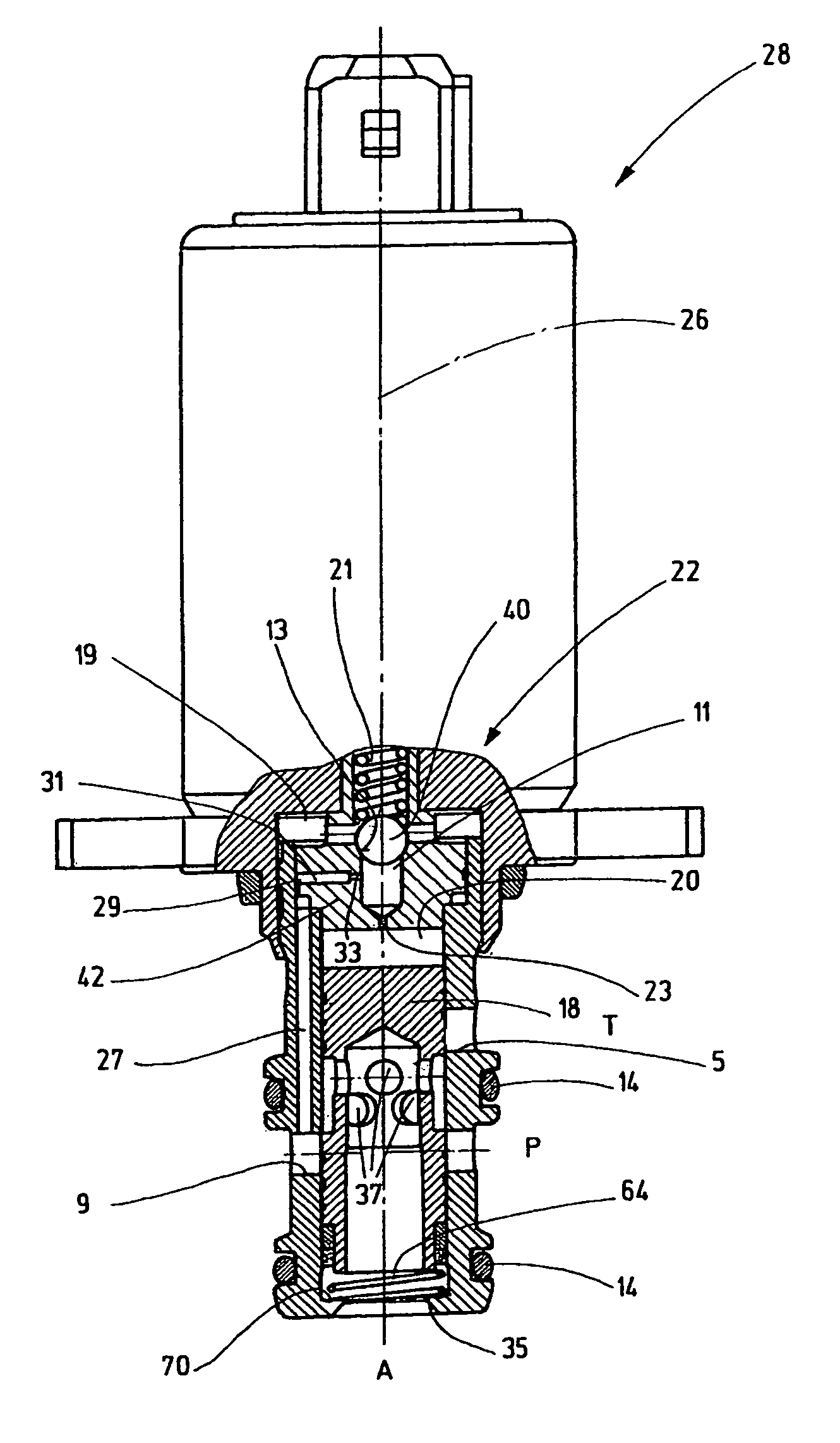
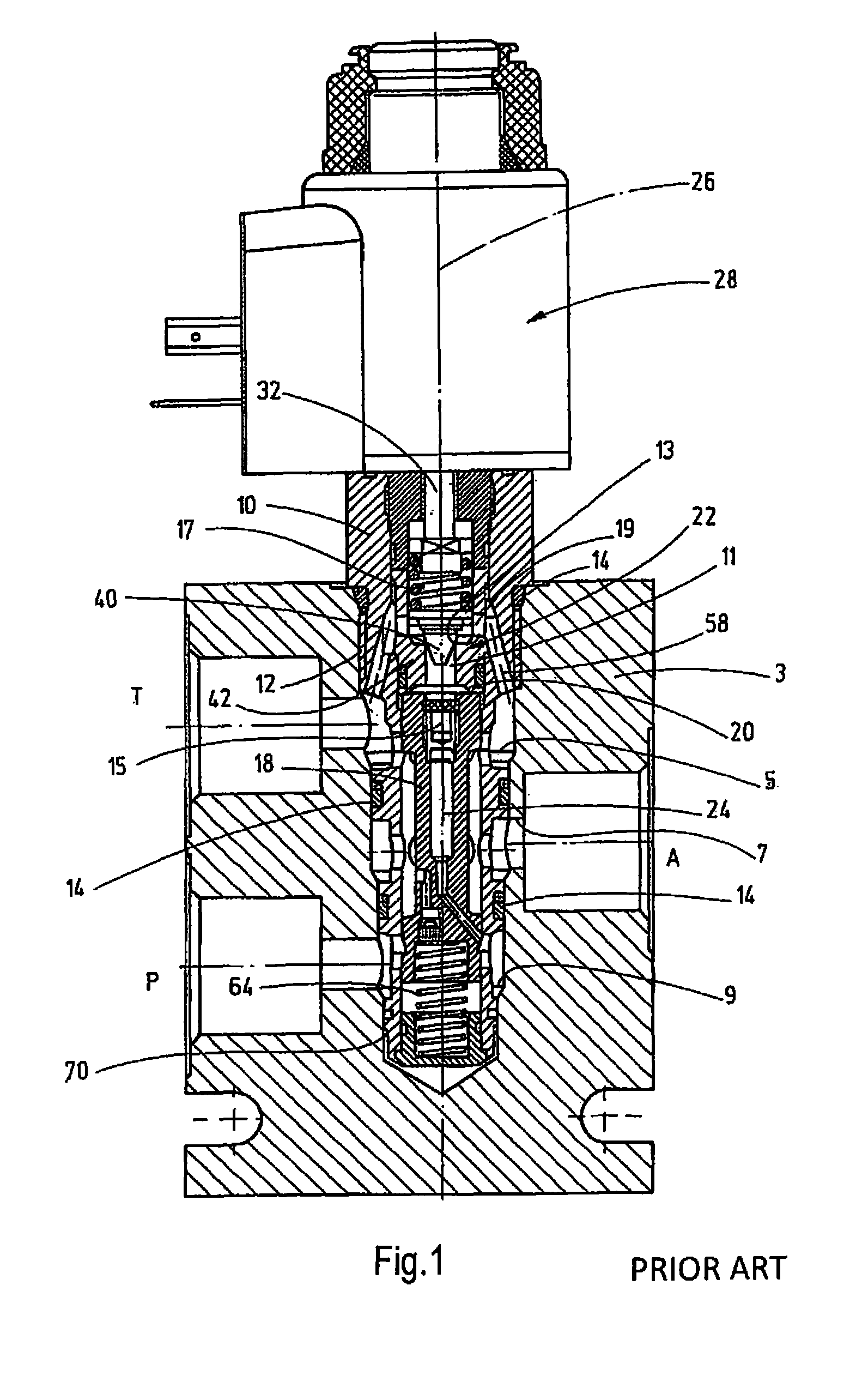
[0019]FIG. 1 shows a proportional pressure control valve of the prior art according to DE 103 25 178 A1. The valve, designed as a screw-in cartridge, has a valve housing 10 which can be screwed into a machine part (not detailed), for example, in the form of a valve block 3, via a screw-in section 12. For the sealed connection to the valve block 3, the valve housing 10 has gaskets 14 on the outer peripheral side seated in the corresponding receivers. The valve housing 10, viewed in the direction of FIG. 1, from top to bottom has radial bores 5 for a tank connection T, radial bores 7 for a user connection A, and radial bores 9 for a pump connection P for a hydraulic pump 16 (cf. FIG. 7). Within the valve housing 10, a control piston 18 is movably guided lengthwise for selective connection of the pump connection P to the user connection A and of the user connection A to the tank connection T.

[0020]To establish a fluid-conducting connection between the pump connection P and a pilot cham...


PUM


Abstract

A proportional pressure control valve includes a valve box (10) having a pump (P), user (A) and reservoir (T) connections. Control piston (18) is guided in a longitudinally displaceably inside the valve box (10) for optionally connecting the pump connection (P) to the user connection (A) and the user connection (A) to the reservoir connection (T). A fluid-carrying connection is established between the pump connection (P) and a pilot chamber (20) of a pilot valve (22). The pilot valve (22) is controlled by a magnet system, especially a proportional magnet system (28). The proportional pressure control valve, for the fluid-carrying connection to the pilot chamber (20), has a bore (27) extending axially inside the wall of the valve box (10) and from a radial bore (9) of the housing (10) forming the pump connection (P).

Description

FIELD OF THE INVENTION[0001]The invention relates to a proportional pressure control valve comprising a valve housing having at least three fluid-conducting connections, particularly in the form of a pump connection, a user connection, and a tank connection. A control piston is guided to be able to move lengthwise within the valve housing for selective connection of the pump connection to the user connection and of the user connection to the tank connection. A fluid-conducting connection is provided between the pump connection and a pilot chamber of a pilot valve. The pilot valve is controllable by a magnet system, in particular a proportional magnet system.BACKGROUND OF THE INVENTION[0002]For applications in which large volumetric flows are controlled, pilot-controlled pressure control valves are preferably used instead of directly controlled valves. A high volumetric flow means both large opening cross sections of the valves for large strokes and large flow forces which counteract...

Claims


Application Information

Patent Timeline
IPC IPC(8): F15B13/043
CPCF16D2500/70418F16D48/02G05D16/2093F15B13/0433F16D2500/5014F15B13/0402F16D2048/0209Y10T137/86702Y10T137/86614G05D16/2024G05D16/2097
Inventor BILL, MARKUSBRUCK, PETERSCHNEIDER, GERD
Owner HYDAC FLUITECHNIK GMBH
Why Eureka
Try Eureka