Wheel suspension for wheeled vehicles

a technology for wheeled vehicles and suspensions, which is applied to resilient suspensions, vehicle springs, vehicle components, etc., can solve the problems of increased buckling and bending strain of pistons, increased ware and shorter life expectancy of sealings belonging to them, and does not facilitate high belly clearance of vehicles. , to achieve the effect of facilitating high belly clearance, minimizing track gauge changes, and improving comfort and driving abilities

Inactive Publication Date: 2014-03-04
BAE SYSTEMS HAGGLUNDS AKTIEBOLAG
View PDF23 Cites 7 Cited by
  • Summary
  • Abstract
  • Description
  • Claims
  • Application Information

AI Technical Summary

Benefits of technology

[0007]An object of the present invention is to suggest an improved wheel suspension, which apart from facilitating high belly clearance and having minimized track gauge changes during inward and outward spring actions of the wheel undercarriage also shall provide improved comfort and driving abilities during simultaneous reduction of buckling and bending strains of the piston with less ware and longer life expectancy on sealings belonging to the hydraulic damping cylinder, and reduced unsprung weight.

Problems solved by technology

This results in increased buckling and bending strain of the piston and increased ware and shorter life expectancy on sealings belonging thereto.
Also, its linked arm system does not facilitate high belly clearance of the vehicle or minimizes the track gauge changes during inward and outward spring actions or results in comfort properties which a hydro-pneumatic spring leg may provide.

Method used


Image

  • Wheel suspension for wheeled vehicles
  • Wheel suspension for wheeled vehicles
  • Wheel suspension for wheeled vehicles

Examples


Embodiment Construction

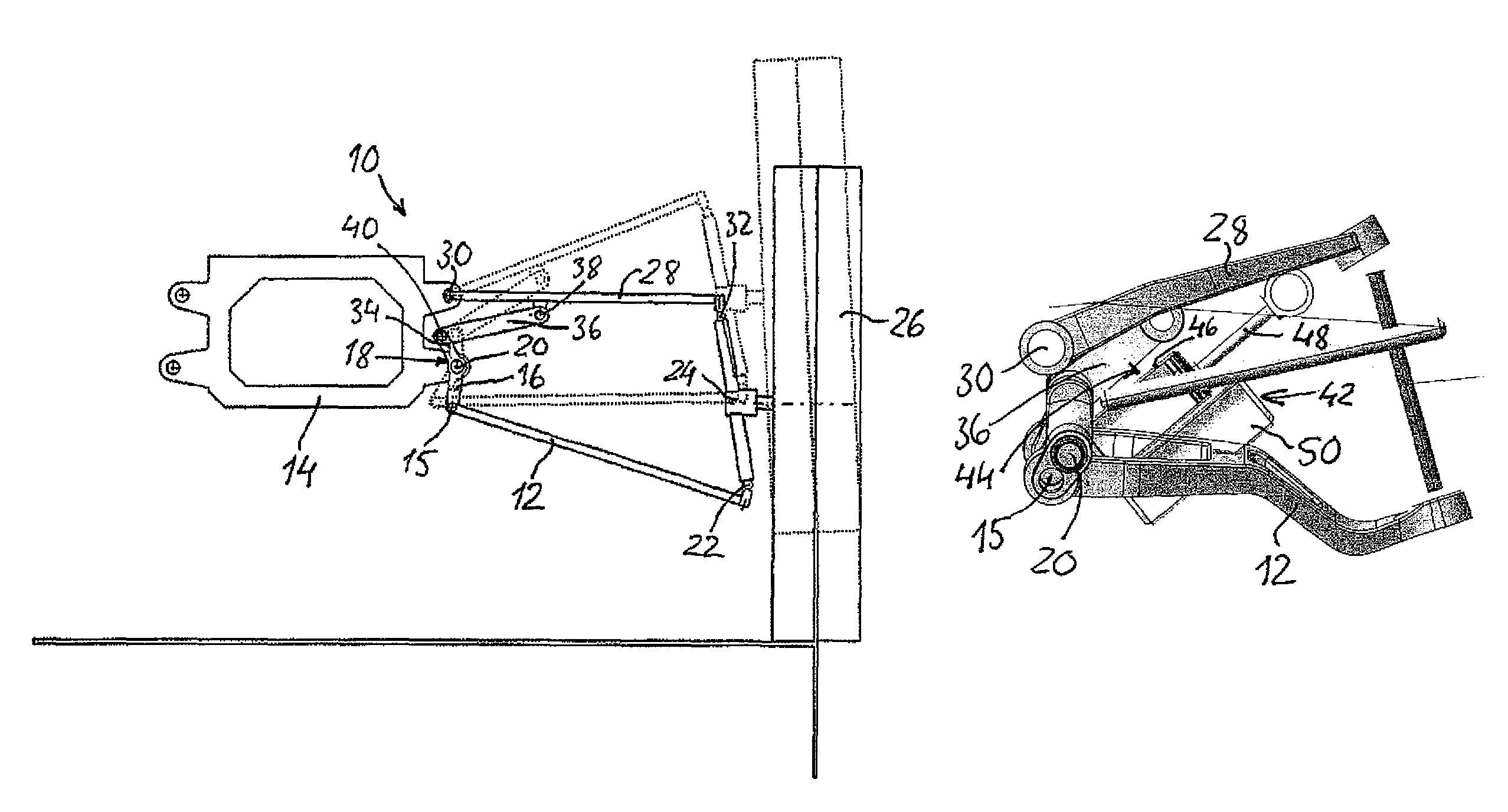
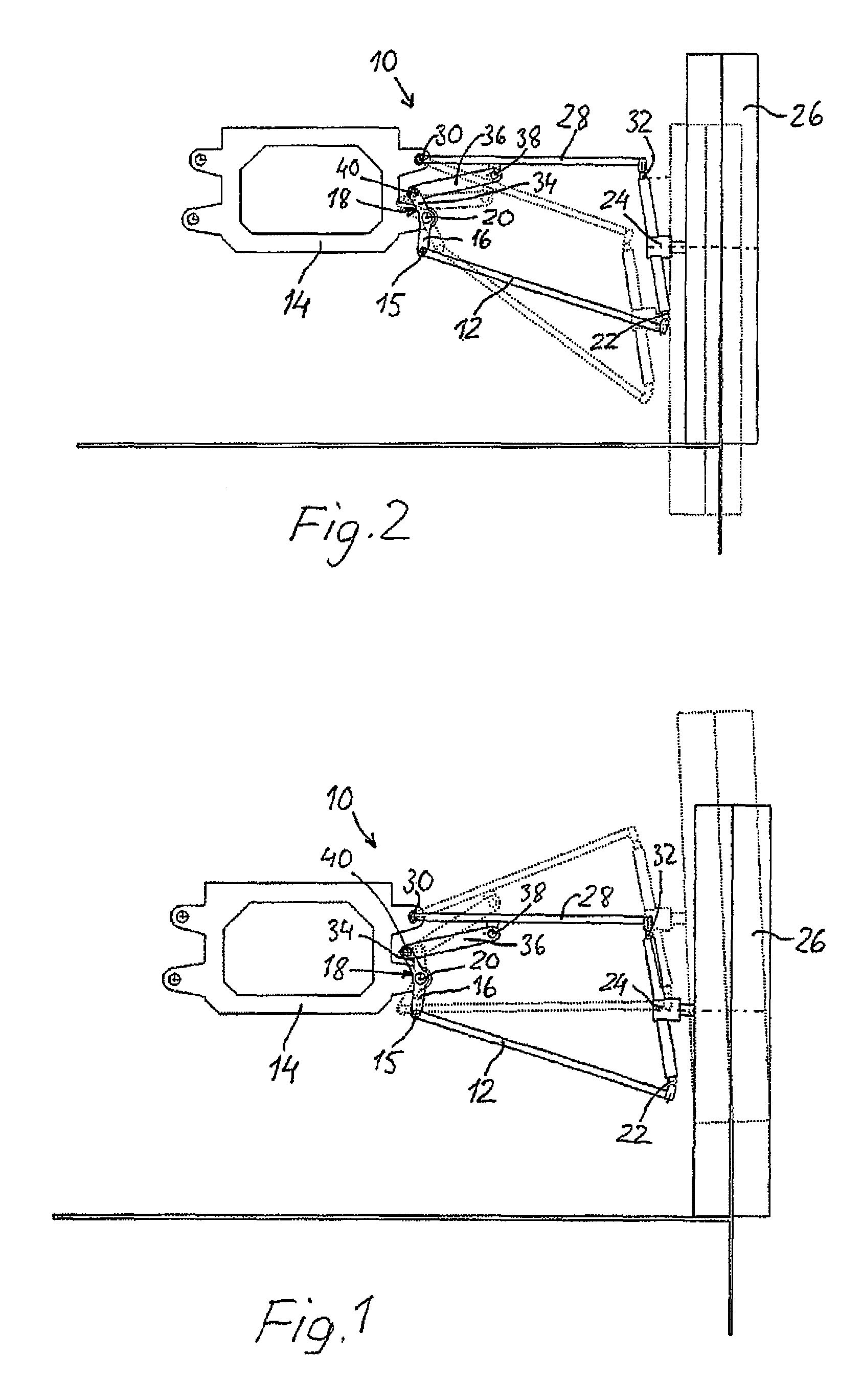
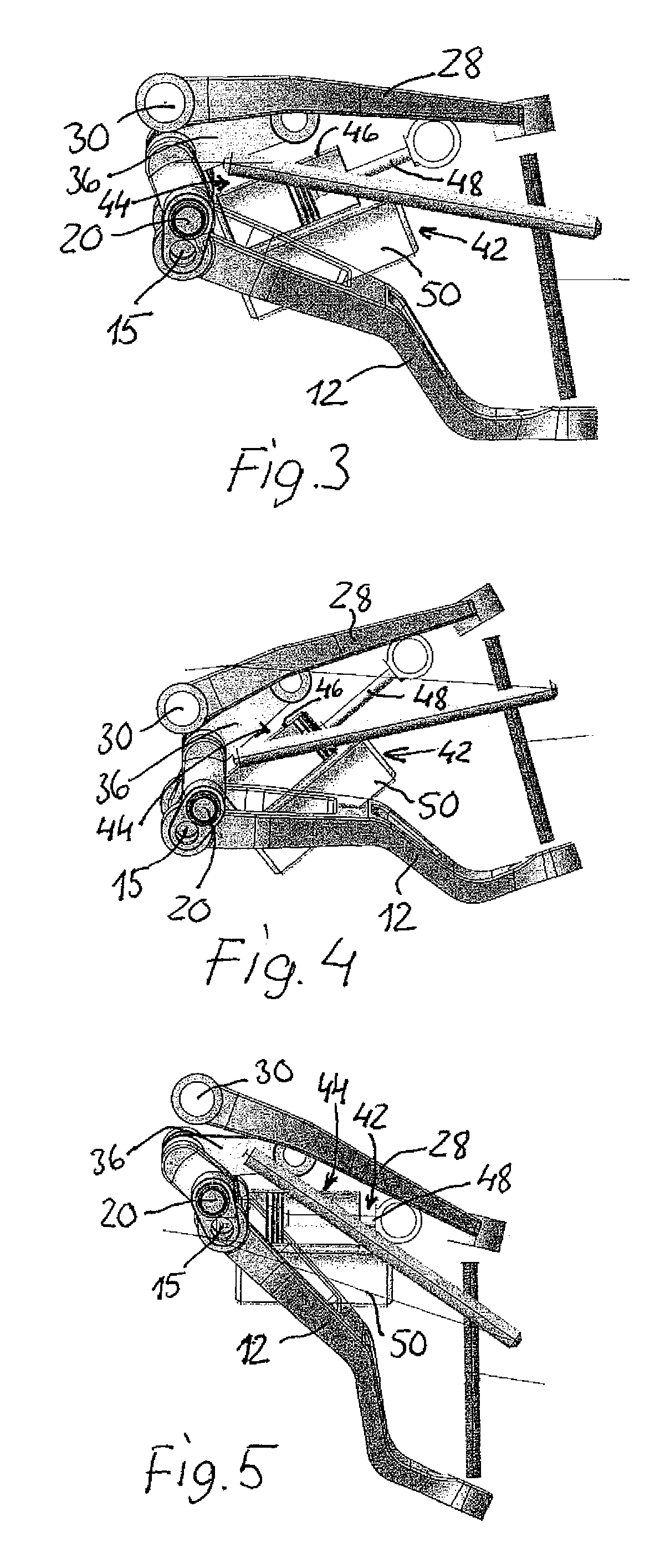
[0016]In FIGS. 1 and 2 an embodiment of the wheel suspension for a wheeled vehicle is generally denoted with 10. The wheel suspension 10 comprises a lower rocking lever 12, which is pivotably and displacably journalled relative to a fixed vehicle frame 14 by being articulately connected at 15 with a lower arm part 16 of a two-armed, track gauge compensating rocker 18, which is substantially vertically oriented and pivotably journalled about a shaft 20 in the frame 14. The outer end of the rocking lever 12 is articulately connected to a lower part of a wheel hub 24, which rotatably supports a wheel 26. The wheel suspension 10 further comprises an upper rocking lever formed as an upper support arm 28, which at its inner end is pivotably journalled in the vehicle frame 14 above a shaft 30 and is articulately connected at 32 with an upper part of the hub 24 of the wheel at its outer end. The upper support arm 28 in turn is connected to an upper arm part 34 of the rocker 18 by means of a...


PUM


Abstract

Wheel suspension for a wheeled vehicle, with a lower rocking lever (12) with an inner end being movably connected to a vehicle frame (14) via a lower arm part (16) of a double armed rocker (18) which is pivotable about a substantially horizontal axle (20) in the vehicle frame, and with an outer end being articulately attached to a lower part of a wheel hub (24), and an upper support arm (28) with an outer end being articulately attached to an upper end of the wheel hub (24), and with an inner end, being articulately connected to the vehicle frame (14). The upper support arm (28) is connected to an upper arm part (34) of the double armed rocker (18) via a coupling link (36), which is articulately connected to the upper support arm (28) as well as the upper arm part (34) of the double armed rocker (18), wherein the lower rocking lever (12) has an inclination obliquely downwardly outwardly from the vehicle frame (14) in a neutral position of the wheel hub (24). A hydro-pneumatically combined spring acting and damping member (42), which comprises a hydraulic piston-cylinder device (44) and a gas spring (50) communicating therewith via restriction members is with its cylinder articulately connected to the vehicle frame (14), while the outer end of the piston stem (48) of the piston-cylinder device is articulately connected to the upper support arm (28).

Description

CROSS REFERENCE TO RELATED APPLICATIONS[0001]This application is a U.S. National Phase patent application of PCT / SE2009 / 051042, filed Sep. 21, 2009, which claims priority to Swedish patent application Serial No. 0802228-7, filed Oct. 20, 2008, all of which are hereby incorporated by reference in the present disclosure in their entirety.TECHNICAL FIELD[0002]The present invention relates to a wheel suspension for wheeled vehicles according to the preamble of claim 1. Such a wheel suspension is known through SE 0700818-8. Particularly, but not exclusively, the invention relates to such a wheel suspension for relatively large and heavy vehicles, in which high belly clearance is desirable as well as minimal track gauge changes during inward and outward spring actions of the wheel suspensions. The wheel suspension according to the invention is usable on steerable as well as non-steerable wheels and driven and non-driven wheels.BACKGROUND ART[0003]Wheel suspensions of vehicles are normally...

Claims


Application Information

Patent Timeline
Patent Type & Authority Patents(United States)
IPC IPC(8): B60G3/26
CPCB60G2200/142B60G7/02B60G2200/144B60G2200/18B60G2204/143B60G2204/421B60G2202/24B60G2202/154B60G2204/4222B60G2200/46B60G11/28B60G2204/128B60G11/265B60G3/26
Inventor CHRISTENSEN, ASSAR
Owner BAE SYSTEMS HAGGLUNDS AKTIEBOLAG
Why Eureka
Try Eureka