Implants, tools, and methods for sinus lift and lateral ridge augmentation

a lateral ridge and lateral ridge technology, applied in the field of dental implants and implantation methods, can solve the problems of difficult surgical operation of bone augmentation procedures and the replacement of maxillary teeth, and achieve the effect of preventing the application of breaking torque and preventing the rotation of the distal tube end

Inactive Publication Date: 2014-03-04
MAXILLENT
View PDF93 Cites 7 Cited by
  • Summary
  • Abstract
  • Description
  • Claims
  • Application Information

AI Technical Summary

Benefits of technology

[0009]Some embodiments of the present invention provide a self-tapping osseointegrated dental implant and minimally-invasive closed sinus lift techniques for augmenting the maxillary alveolar ridge while reducing the risk of perforating the Schneiderian membrane and of infection. The dental implant is shaped so as to define a lumen therethrough having a distal opening through a distal external surface of a distal portion of the implant. During an implantation procedure, a surgeon advances the implant into a bore in the ridge until the distal implant end forms an opening through the top of the ridge to below the Schneiderian membrane, thereby bringing the distal opening into fluid communication with a surface of the membrane facing the ridge.

Problems solved by technology

Replacement of the maxillary teeth is often a challenging surgical procedure when the remaining maxillary bone has insufficient height to support the implant.
Bone augmentation procedures are often surgically difficult to perform, and are associated with complications, including infection of the maxillary sinus.
This is often difficult, because of the delicacy of the membrane, and the restricted access afforded by the closed approach.

Method used


Image

  • Implants, tools, and methods for sinus lift and lateral ridge augmentation
  • Implants, tools, and methods for sinus lift and lateral ridge augmentation
  • Implants, tools, and methods for sinus lift and lateral ridge augmentation

Examples


Embodiment Construction

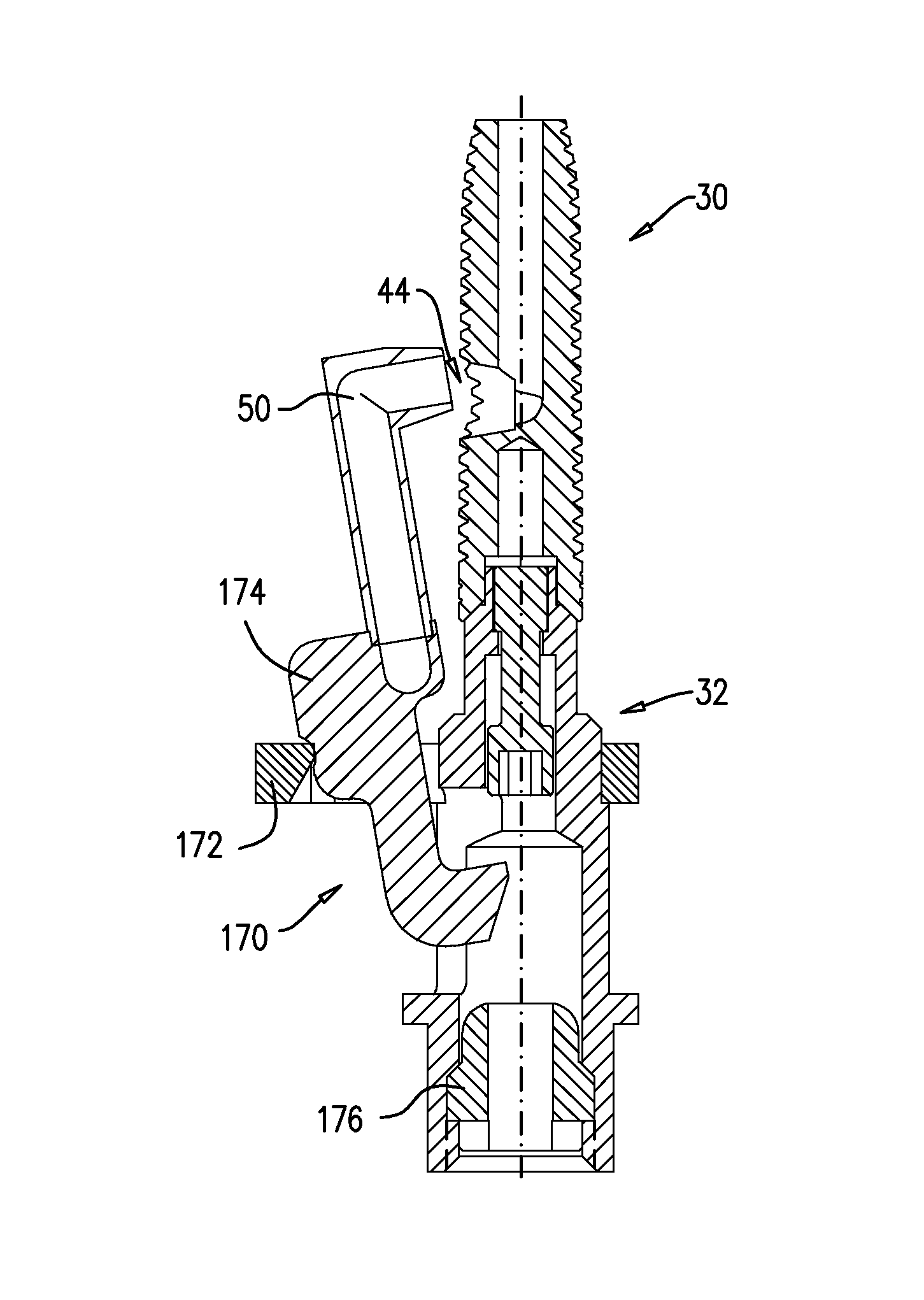
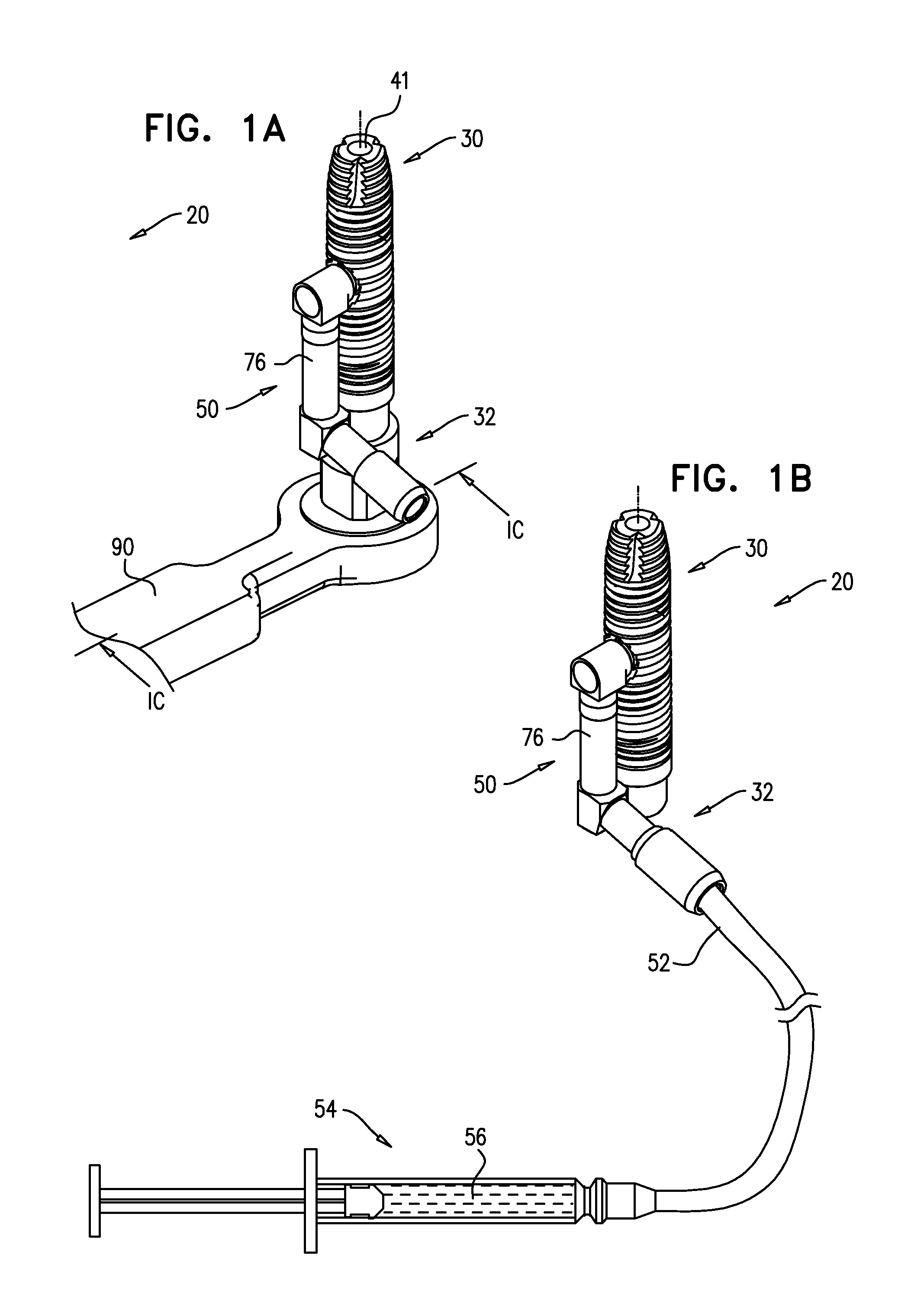
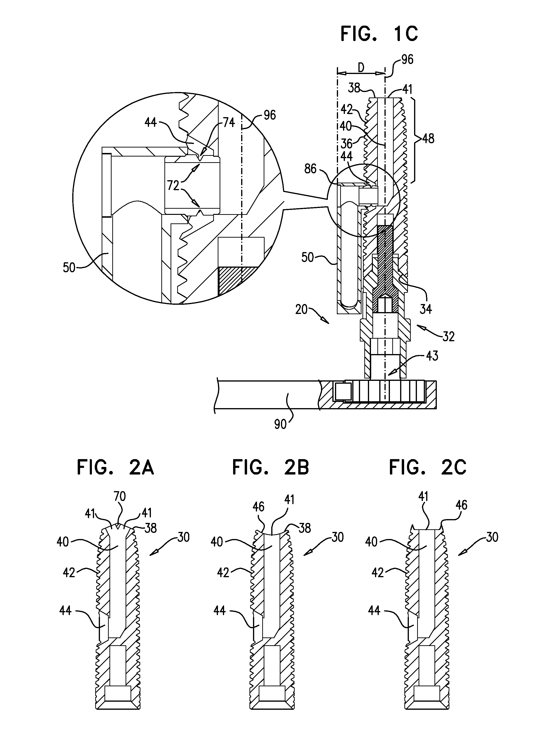
[0170]FIGS. 1A-C are schematic illustrations of a dental implant system 20, in accordance with an embodiment of the present invention. FIGS. 1A-B are isometric views of the system, andFIG. 1C is a cross-sectional view of FIG. 1A along line IC-IC. System 20 comprises a dental implant 30, which is typically shaped so as to define a lumen 40 therethrough that is open through a distal opening 41 to a distal portion 48 of the implant that extends from a distal implant end 38 of the implant along up to 50% of a longitudinal length of the implant, such as up to 30% of the length, up to 15% of the length, or up to 5% of the length. For some applications, distal portion 48 has a longitudinal length of up to 8 mm, such as up to 6 mm, up to 4 mm, or up to 2 mm, e.g., 5 mm or 8 mm. As used herein, including in the claims, the “distal” end of the implant is the end that is inserted first into a bone, such as an alveolar ridge, and is sometimes referred to in the art as the apical end, and the “p...


PUM


Abstract

Apparatus is provided that includes a dental implant having a lateral external surface. The implant is shaped so as to define a lumen therethrough having a lateral opening through the lateral external surface. The apparatus further includes a retaining element, and a delivery tube having a distal tube end. The retaining element is configured to assume (a) a first position in which the retaining element removably couples the distal tube end to the implant such that the delivery tube is in fluid communication with the lumen via the lateral opening, and (b) a second position in which the retaining element does not couple the distal tube end to the implant. Other embodiments are also described.

Description

CROSS-REFERENCE TO RELATED APPLICATIONS[0001]The present invention is:[0002](a) a continuation-in-part of International Application PCT / IL2010 / 000252, filed Mar. 24, 2010, which is a continuation-in-part of (i) U.S. application Ser. No. 12 / 485,199, filed Jun. 16, 2009, now U.S. Pat. No. 8,029,284, and (ii) International Application PCT / IL2009 / 000931, filed Sep. 29, 2009; and[0003](b) a continuation-in-part of U.S. application Ser. No. 13 / 040,440, filed Mar. 4, 2011, now U.S. Pat. No. 8,356,994, which is a continuation of U.S. application Ser. No. 12 / 240,353, filed Sep. 29, 2008, now U.S. Pat. No. 7,934,929.[0004]All of the above-mentioned applications are assigned to the assignee of the present application and are incorporated herein by reference.FIELD OF THE APPLICATION[0005]The present invention relates generally to dental implants and implantation methods, and specifically to minimally-invasive implants and implantation methods for sinus lift and lateral ridge augmentation proced...

Claims


Application Information

Patent Timeline
Patent Type & Authority Patents(United States)
IPC IPC(8): A61C8/00
CPCA61C8/0018A61C19/06A61C8/0022A61C8/0092A61C8/006A61C8/0074A61C8/0039A61C19/063
Inventor UCHITEL, ILANFOSTICK, GIDEONBETTER, HADARGROSS, YOSSI
Owner MAXILLENT
Why Eureka
Try Eureka