Jaw movement mechanism and method for a surgical tool

a technology of jaw movement and surgical tool, which is applied in the field of surgical tools, can solve the problems of reducing the force available from the jaw, limiting the degree and extent of jaw movement, and losing the mechanical force applied to the jaw movement mechanism, so as to reduce the amount of frictional sliding contact, enhance the mechanical force transferring capability and efficiency, and reduce the effect of friction

Active Publication Date: 2014-03-04
CONMED CORP
View PDF140 Cites 849 Cited by
  • Summary
  • Abstract
  • Description
  • Claims
  • Application Information

AI Technical Summary

Benefits of technology

[0011]The present invention substantially reduces the amount of frictional sliding contact between pins moving in slots of a jaw movement mechanism of a surgical tool of the type which opens and closes the jaws with parallel movement when the jaws are relatively close to one another and opens and closes the jaws with pivotal movement when the jaws are relatively farther away from one another. The present invention also enhances the mechanical force transferring capability and efficiency of the type of jaw movement mechanism which uses a pin in a slot to move a jaw member by reducing the amount of friction created by the pin moving in the slot. Furthermore, the present invention achieves more compression force by the jaws on the tissue in relation to the amount of force transferred through the relative longitudinal reciprocating movement of the shaft housing and the shaft rod.
[0013]Because the pivot link restrains the movable jaw against longitudinal movement, the energy losses due to frictional contact between the pins in the slots to maintain the longitudinal position of the relatively movable jaw is eliminated or substantially reduced, thereby reducing the amount of frictional sliding contact between pins moving in the slots and correspondingly increasing the amount of force available to move the jaws. The mechanical force transferring capability and efficiency is improved, and more compression force from the jaws on the tissue is available in relation to the amount of force generated at the handle assembly.
[0015]Additional features of both the apparatus and method of the present invention involve creating a fully opened position of the jaws where the straight working surfaces extend at an angular orientation to one another at a relative great transverse separation distance from one another and to create a fully closed position where the working surfaces extend in a parallel orientation to one another at a relatively adjacent transverse distance from one another; creating an intermediate position where the working surfaces extend in the parallel orientation to one another at a relatively greater transverse distance and at a relatively lesser transverse distance than the position of the working surfaces in the fully closed and fully opened positions, respectively; maintaining the parallel orientation of the working surfaces during relative transverse movement of the jaws between the fully closed and intermediate positions; farther separating the first and second pins in the first and second slots with movement of the jaw members from the intermediate position to the fully closed position; and using an interior rod as the relatively stationary shaft member, positioning the interior rod within a sleeve housing, and constraining the sleeve housing and the interior rod to prevent relative rotational movement while permitting relative longitudinal reciprocating movement.

Problems solved by technology

The mechanical geometry involved in this conversion usually diminishes the force available from the jaws compared to the force available due to the relative movement of the shaft housing and shaft rod.
Some of the mechanical force applied to the jaw movement mechanism is lost due to frictional resistance between moving parts of the jaw movement mechanism.
The narrowness of the shaft assembly, jaw movement mechanism and jaws also limits the degree and extent of movement of the jaws.
A drawback of the pin and slot type of jaw movement mechanism is that a significant amount of the force from relative longitudinal reciprocating movement of the shaft housing and the shaft rod is lost due to sliding frictional contact of the pins with the slots.
The geometric orientation of the slots involves portions which are inclined with respect to one another, and the movement of the pin along the inclined portion of the slot generates substantial friction and reduces the amount of force available to move the jaws.
This frictional sliding contact reduces the mechanical efficiency of the jaw movement mechanism.
The amount of efficiency lost by the frictional engagement of the pins with the slots can reduce the amount of force available on the jaws to the point where the pressure is insufficient for tissue sealing.

Method used


Image

  • Jaw movement mechanism and method for a surgical tool
  • Jaw movement mechanism and method for a surgical tool
  • Jaw movement mechanism and method for a surgical tool

Examples


Embodiment Construction

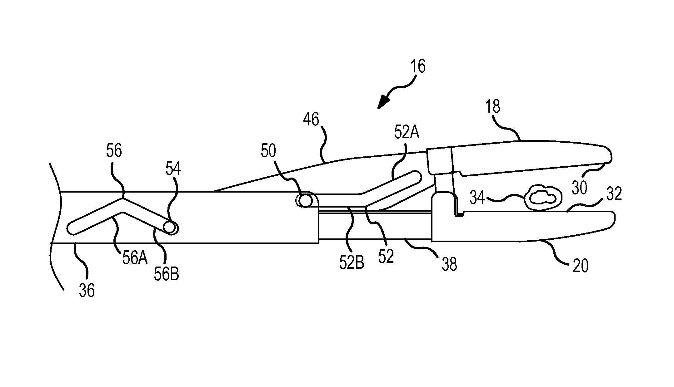
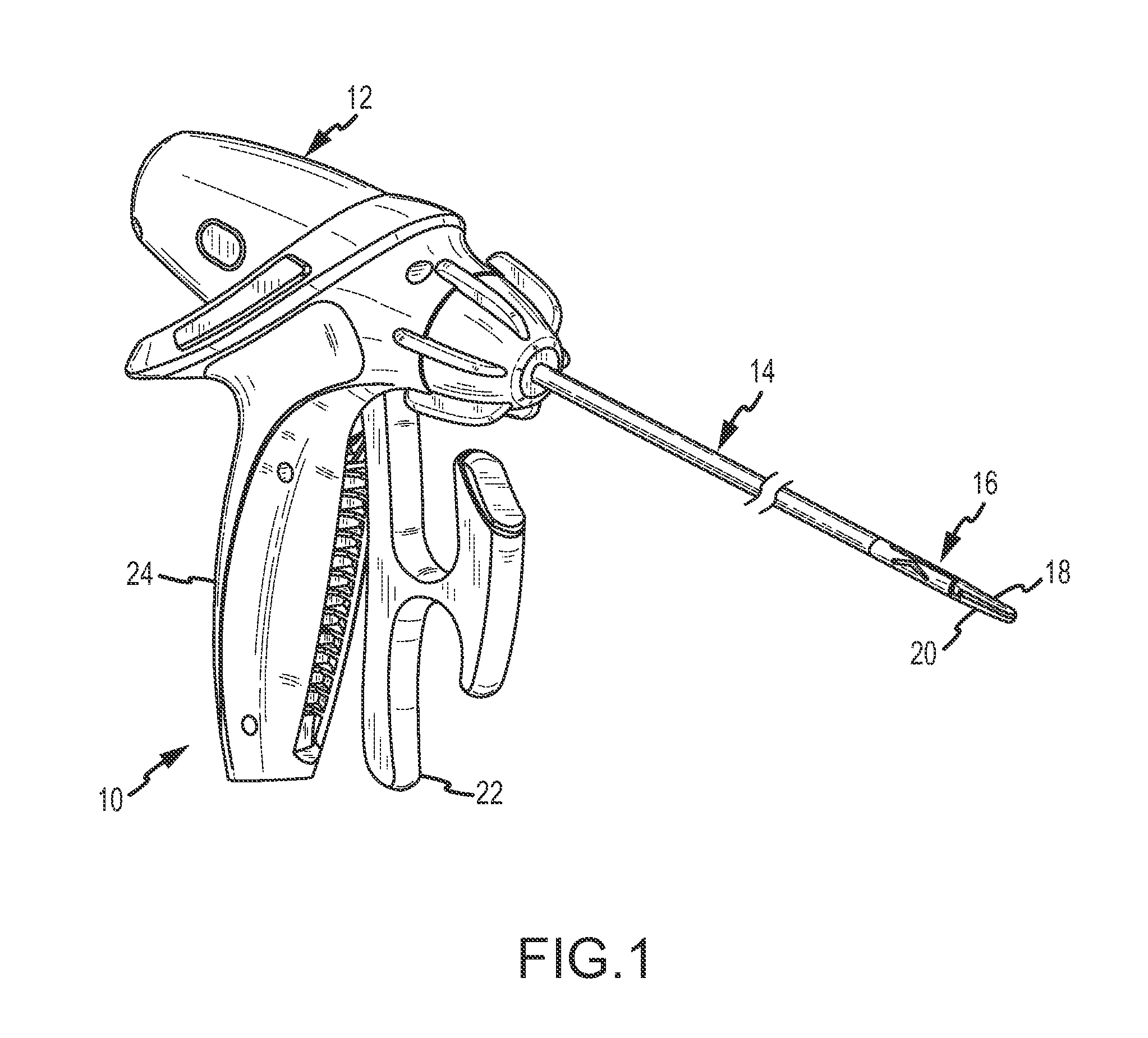
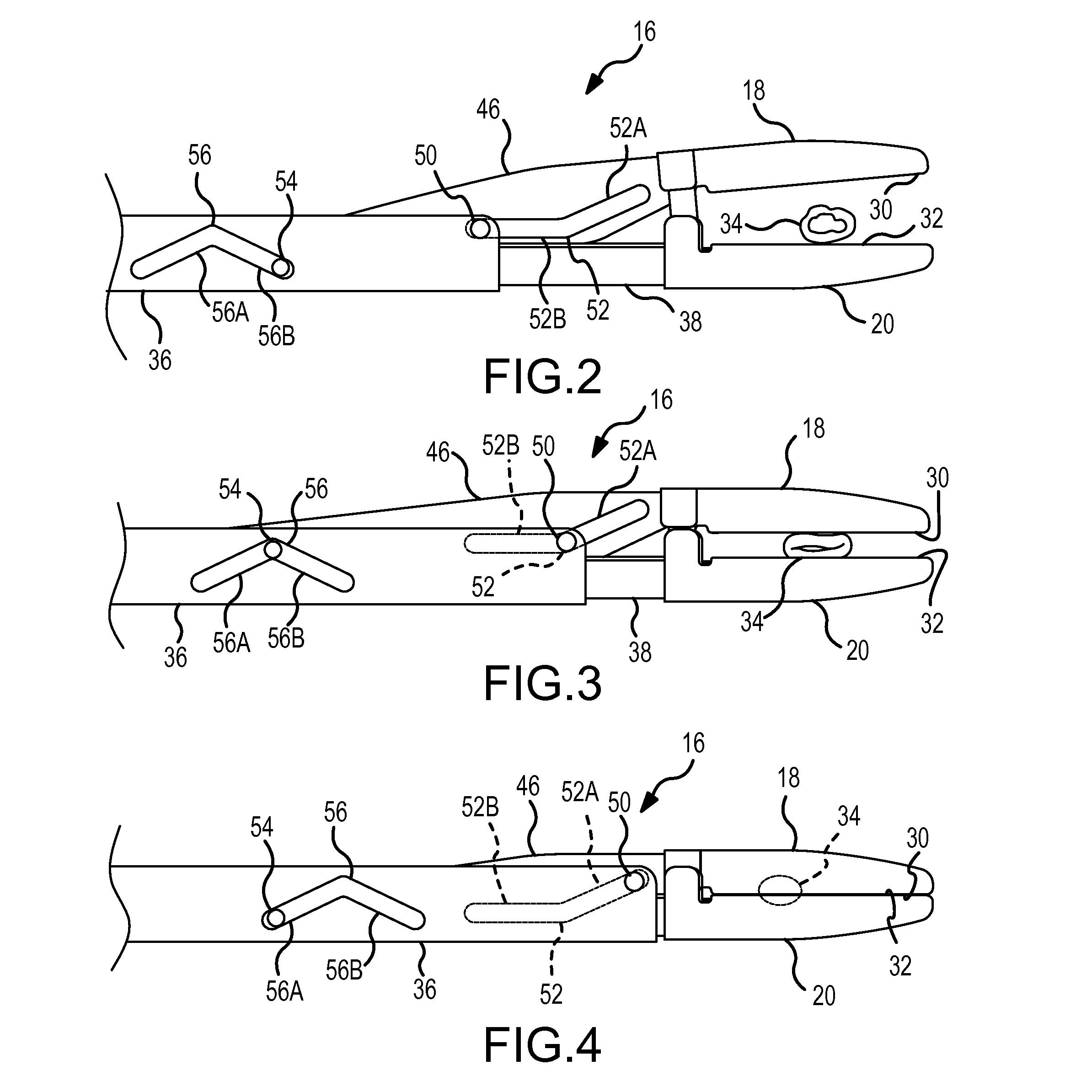
[0023]A surgical tool 10 which is useful in performing minimally invasive surgical procedures and which incorporates the present invention, is shown in FIG. 1. The surgical tool 10 includes a handle assembly 12, a shaft assembly 14 connected to the handle assembly, a jaw movement mechanism 16 located at a distal end of the shaft assembly 14, and jaws 18 and 20 connected to and moved by the jaw movement mechanism 16. The movement of the jaws 18 and 20 is shown in FIGS. 2-4.

[0024]The handle assembly 12 includes a movable lever 22 which pivots relative to a fixed handgrip 24, as shown in FIG. 1. The shaft assembly 14 includes longitudinally relatively movable shaft members in the form of a sleeve housing 26 (FIG. 5) within which an interior rod 28 (FIG. 5) is located. An internal mechanism (not shown) within the handle assembly 12 converts the relative pivoting movement of the lever 22 and the handgrip 24 into relative longitudinal reciprocating movement of the sleeve housing 26 and th...


PUM

PropertyMeasurementUnit
sizesaaaaaaaaaa
sizesaaaaaaaaaa
displacementaaaaaaaaaa

Abstract

A jaw movement mechanism for surgical tools has improved mechanical efficiency and other advantages. The jaw movement mechanism controls the orientation and position of a movable jaw relative to a fixed jaw through a range of movement of the movable jaw. The jaws maintain a parallel orientation throughout a portion of the range of movement of the movable jaw. The jaws maintain an angular relationship throughout a portion of the range of movement of the movable jaw.

Description

CROSS REFERENCE TO RELATED APPLICATION[0001]This invention is related to an invention described in U.S. patent application Ser. No. 12 / 842,399, titled Surgical Tool with Crossbar Lever, filed concurrently herewith and assigned to the assignee hereof. The subject matter of this related patent application is incorporated herein by this reference.FIELD OF THE INVENTION[0002]This invention relates to a surgical tool having jaws which grasp or otherwise manipulate tissue during a surgical procedure. More particularly, the invention relates to a surgical tool in which the jaws are positioned at one end of a long and narrow shaft assembly and a handle assembly operating mechanism is connected at the other end of the shaft to operate the jaws, thereby allowing the shaft assembly to be inserted through a cannula or endoscope when performing laparoscopic, endoscopic or other minimally invasive surgical procedures. Even more specifically, the present invention relates to a new and improved jaw...

Claims


Application Information

Patent Timeline
Patent Type & Authority Patents(United States)
IPC IPC(8): A61B17/00
CPCA61B18/1445A61B2018/0063A61B17/29A61B2017/2936A61B2017/2944A61B2017/2939A61B2018/145
Inventor DONNIGAN, STEPHENSUGALSKI, ERICHOLVERSON, ERIKKOPLIN, RANDALLGREGOR, MICHAEL
Owner CONMED CORP
Why Eureka
Try Eureka