Pointing device for improved accuracy

a pointing device and accuracy technology, applied in the field of pointing devices, can solve the problems of easy affecting the accuracy of pointing devices, so as to achieve smooth movement and reduce the occurrence of pointing errors

Active Publication Date: 2014-03-04
SHIN-ETSU POLYMER CO LTD
View PDF4 Cites 0 Cited by
  • Summary
  • Abstract
  • Description
  • Claims
  • Application Information

AI Technical Summary

Benefits of technology

[0010]With consideration of the situation described above, the present application is provided. An object of the present application is to provide a pointing device in which pointing errors are lowered.
[0011]The inventor of the present application has examined causes for the pointing errors discussed above. As a result, the inventor identified the causes. The causes are that the amount of pressure in the vertical direction is larger at the time of strongly driving the sensor when a rubber sensor is driven within a level plane. When the amount of pressure in the vertical direction is large, a contact region with a circular electrode is extremely large and easily becomes oval shaped. Force for pressing the spherical part, which exists at a lower surface of the rubber sensor, toward the circular electrode is changed according to an operation direction and strength of the rubber sensor. Therefore, an area and a shape of the contact region between the spherical part and the circular electrode are changed. As a result, the possibility for the occurrence of errors, i.e. a detecting location is different from an intended driving direction of an operator, is increased. In view of this, the inventor determined that it is necessary to keep an almost constant contact region regardless of an operation direction when the rubber sensor is driven within a level plane. Specifically, the following solutions are employed.
[0017]Yet other embodiment of a pointing device according to the present application is as follows: an inner bottom surface of a concave part that covers the top part of the location pointing driving body in the slide member from above has an outer circumferential concave part at an inner bottom corner that sags from the center of the inner bottom upper surface, and when the slide member is slid, the outer circumferential concave part is configured to enable the top part of the location pointing driving body to move smoothly.
[0018]According to the present application, pointing errors of a pointing device can be lowered.

Problems solved by technology

The same problems also occur on the Y-axis.
Therefore, pointing errors easily occur at the time of detecting a pointing location.
As a result, the possibility for the occurrence of errors, i.e. a detecting location is different from an intended driving direction of an operator, is increased.

Method used


Image

  • Pointing device for improved accuracy
  • Pointing device for improved accuracy
  • Pointing device for improved accuracy

Examples


first embodiment

1. First Embodiment

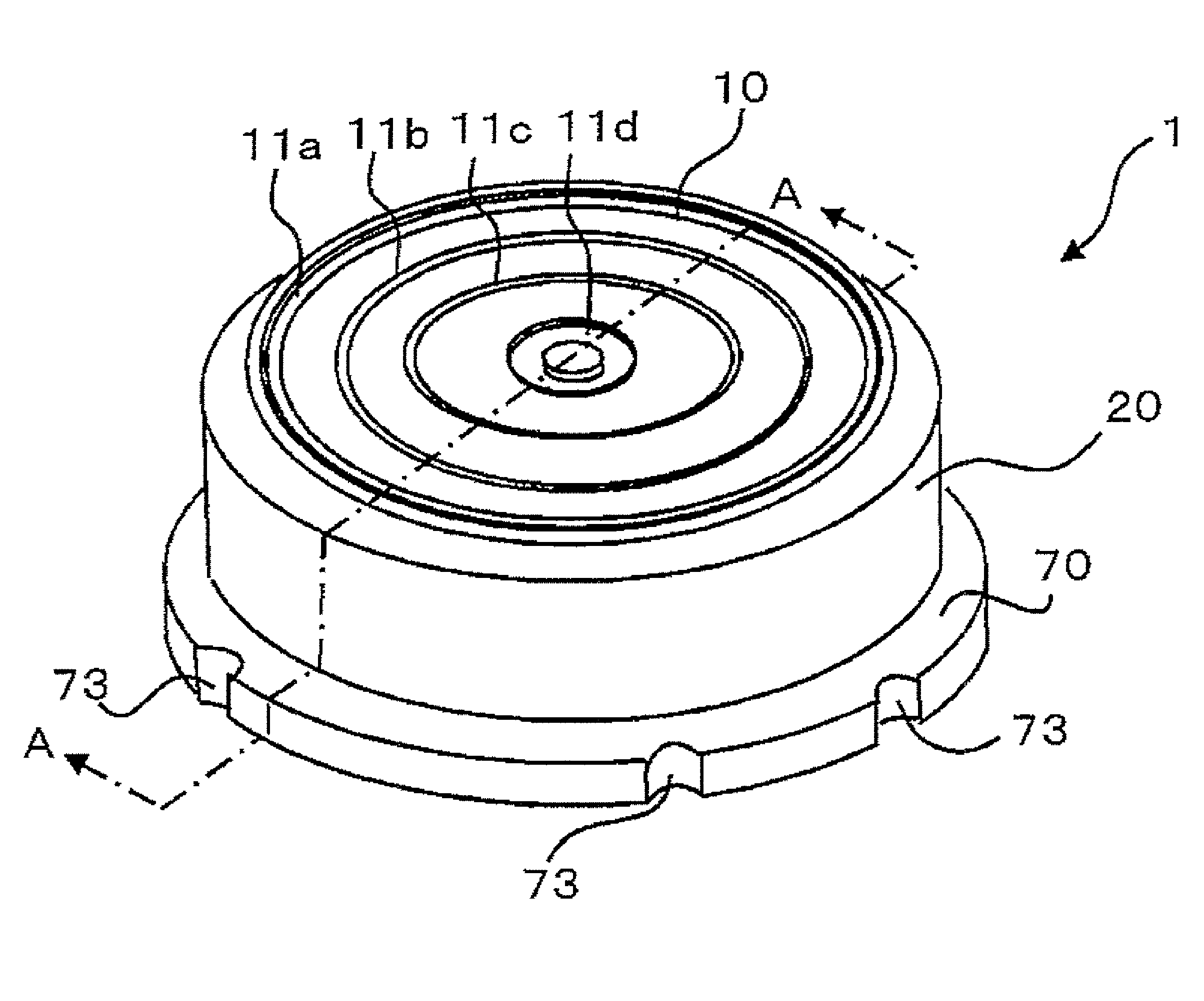
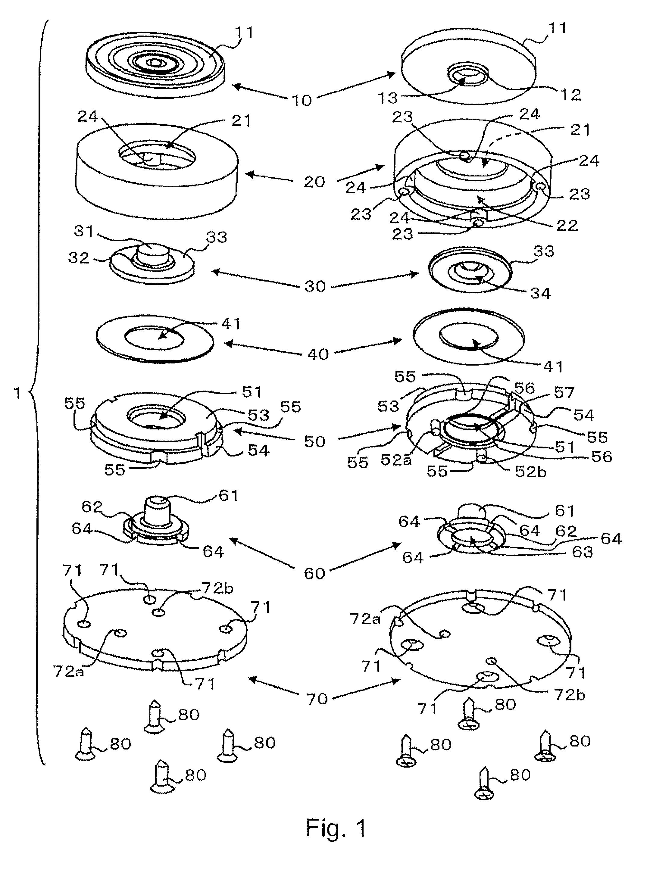
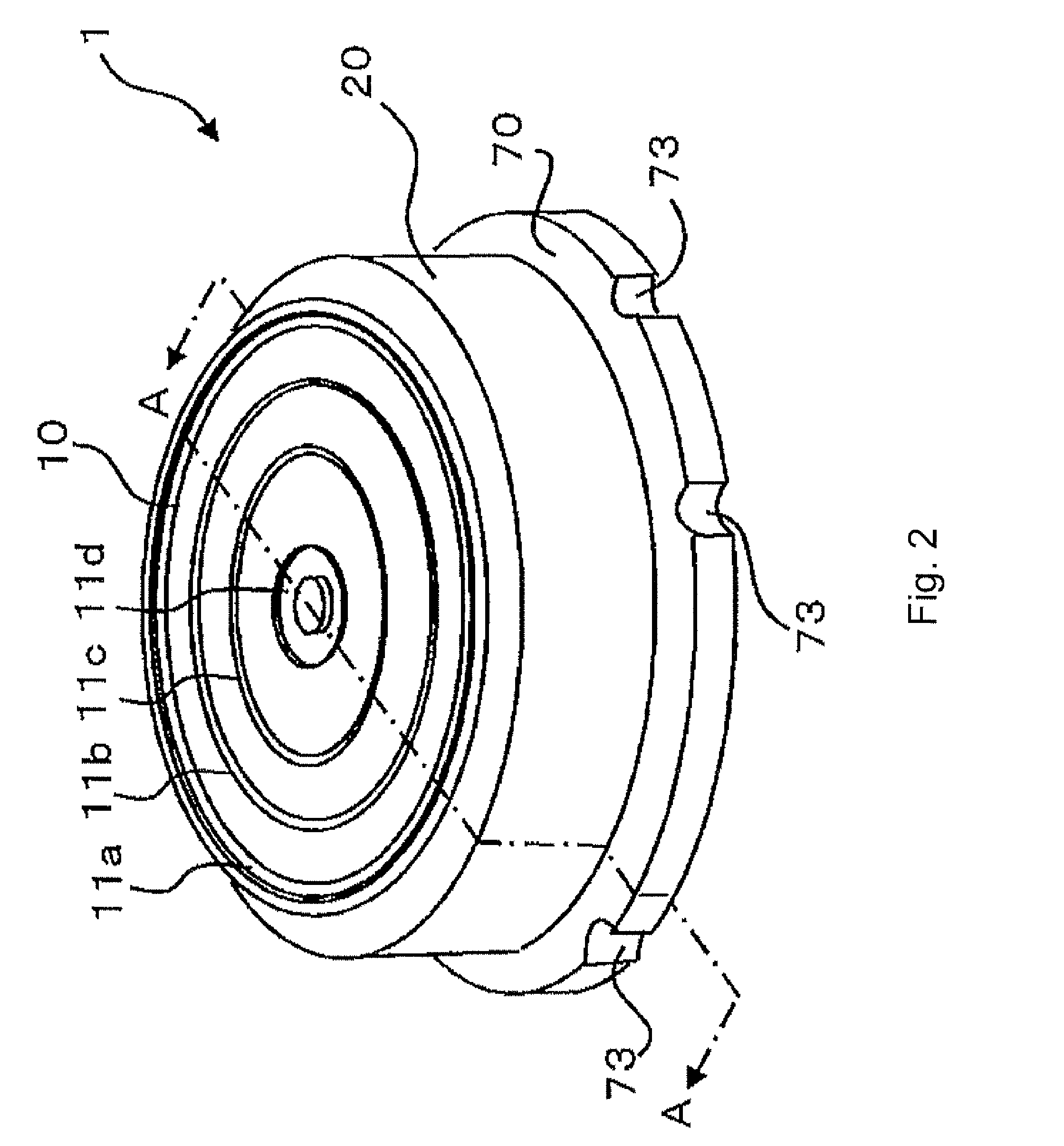
[0039]FIG. 1 is an exploded perspective view of a pointing device according to a first embodiment. Left side configuration drawings are seen from an obliquely upward direction. Right side configuration drawings are seen from an obliquely downward direction. FIG. 2 and FIG. 3 are, respectively, a perspective view and a side plan view of a pointing device shown in FIG. 1 after assembly. FIG. 4 is a sectional view of a pointing device taken along line A-A shown in FIG. 2. Hereinafter, each direction for up, down, right, and left is defined as an up direction, a down direction, a right direction, and a left direction in FIG. 4, respectively.

[0040]As shown in FIG. 1, a pointing device 1 according to the first embodiment is configured with a combination of an actuator cap 10, a housing 20, a slide member 30, a ring sheet 40, a clamp ring 50, a location pointing driving body 60, and a PCB 70 in order from top to bottom.

[0041]The actuator cap 10 is made of resin and has a...

second embodiment

2. Second Embodiment

[0074]FIG. 12 is an exploded perspective view of a pointing device according to a second embodiment. FIG. 13 is a sectional view of a pointing device shown in FIG. 12 taken along the same line as line A-A for a pointing device shown in FIG. 2. In the same manner as the first embodiment, hereinafter, each direction for up, down, right, and left is defined as an upper direction, a down direction, a right direction, and a left direction in FIG. 13, respectively.

[0075]A pointing device 100 according to the second embodiment is configured with a combination of an actuator cap 110, a case plate 120, a slide member 130, a ring sheet 140, a housing 150, a clamp ring 160, a location pointing driving body 170, and a PCB 180 in order from top to bottom.

[0076]The actuator cap 110 is made of resin and has a configuration in which a cylindrical body 112 that has a sufficiently smaller diameter than that of an operation plate 111 is jointed at a bottom surface of the operation ...


PUM


Abstract

A pointing device includes a first ground potential electrode; a second electrode for applying a voltage; a third electrode for measuring an electrical potential; a printed circuit board on which the first through the third electrodes are provided; a location pointing driving body that is provided on the printed circuit board and that is configured with a conductive part and that contacts the first and second electrodes, and a spherical part; a slide member that is located to cover a top part of the location pointing driving body and that is configured to drive the location pointing driving body by being slidable within a plane parallel to the printed circuit board; and a pressing force restriction member that is configured to restrict pressing force from the spherical part to the printed circuit board by receiving force from the slide member in the pressing direction.

Description

CROSS REFERENCE[0001]The present application is related to, claims priority from and incorporates by reference Japanese patent application number 2009-208852, filed on Sep. 10, 2009.TECHNICAL FIELD[0002]The present application relates to a pointing device that can point any direction on a plane, and that can be used as an operation device for an electronic device.RELATED ART[0003]Pointing devices have been widely used as an input device of, for example, personal computers, portable communication terminals, and game systems. Specifically, a pointing device in which a stick-shaped operating device is freely movable on at least an X-Y plane has been widely known as a very useful operating device to freely move an object displayed on a display. Such a pointing device has a wide variety of configurations. A pointing device in which a matrix (X, Y) of a pointing location is detected by contact locations in an X direction and a Y direction through contacting a nearly spherical part of a co...

Claims


Application Information

Patent Timeline
Patent Type & Authority Patents(United States)
IPC IPC(8): G06F3/0354G09G5/00G06F3/033G06F3/0338
CPCG06F3/03548G06F3/0338
Inventor ANDO, HITOSHI
Owner SHIN-ETSU POLYMER CO LTD
Why Eureka
Try Eureka