Temperature sensor

a technology of temperature sensor and sensor body, which is applied in the field of temperature sensor, can solve the problems of responsiveness and temperature sensitivity deterioration, and achieve the effects of preventing the separation or movement of the element from the front end of the tube, preventing the deterioration of responsiveness or temperature sensitivity, and eliminating cemen

Active Publication Date: 2014-03-11
NGK SPARK PLUG CO LTD
View PDF20 Cites 10 Cited by
  • Summary
  • Abstract
  • Description
  • Claims
  • Application Information

AI Technical Summary

Benefits of technology

[0025]According to the present invention, through deformation of the elastic seal member having rubber-like elasticity, the seal member presses the rear end of the insulation sheath frontward, directly or via another member, by means of the frontward-oriented surface of the seal member, whereby the temperature sensor element is pressed against the front end of the tube via the insulation sheath. Thus, even when a fixing filler (e.g., heat-resistant cement; hereinafter, also referred to as cement) is charged between the inner circumferential surface of a portion of the tube located toward the front end of the tube and each of the element and the outer circumferential surface of a portion of the insulation sheath located toward the front end of the insulating sheath, and the cement is broken into pieces and scatters when vibrated in the course of use of the sensor, according to the present invention, in contrast to the above-mentioned conventional technique, separation or movement of the element from the front end of the tube can be prevented. Therefore, since heat transferability from the front end of the tube to the element is not damaged, deterioration in responsiveness or temperature sensitivity can be prevented. That is, the temperature sensor of the present invention is configured to stably maintain a state in which the element contained in the tube is in contact with the front end of the tube. Thus, the cement can be eliminated, depending on the shape of a front end portion of the tube or the gap (dimension) between the inner circumferential surface of the front end portion of the tube and each of the element and the outer circumferential surface of the insulation sheath. That is, the cement can be eliminated by minimizing the gap. In this case, the structure can be simplified, and a cement charging step and a cement drying step can be eliminated, whereby the efficiency of assembly can be improved. The temperature sensor element is configured such that electrode wires are connected to a temperature-sensing element, such as a thermistor. In the present invention, the temperature sensor element is not limited to an exposed temperature sensor element, includes a temperature sensor element coated with glass or an insulating ceramic.
[0026]Also, as described above, according to the present invention, by virtue of rubber-like elasticity effected through deformation of the elastic seal member, the frontward-oriented surface of the elastic seal member presses the rear end of the insulation sheath. This structural feature prevents lateral oscillation of the rear end of the insulation sheath. Therefore, this structural feature also prevents breakage of the core wire(s) projecting from the rear end of the insulation sheath. Further, an independent component is not required for pressing the rear end of the insulation sheath. Thus, a temperature sensor having excellent vibration resistance and durability can be implemented without increasing cost.
[0027]In place of utilizing deformation (rubber-like elasticity) of the elastic seal member having rubber-like elasticity as in the case of the present invention, the use of a hard member (hereinafter, referred to as a resin member) which cannot be deformed or which resists being deformed, such as a resin member, for pressing the sensor element against the front end of the tube might be considered. However, when such a resin member is used, unless the dimensional accuracy of the resin member is very high, the element cannot effectively press against the front end of the tube, or the element is pressed with excessive force against the front end and may brake. By contrast, in the case of using a member having rubber-like elasticity such as the elastic seal member of the present invention, even if a relatively large dimensional error is involved in the course of manufacture, the element can be readily pressed against the front end of the tube with an appropriate force and without breaking the element. Also, if the seal member is formed of the resin, upon occurrence of a dimensional change associated with deterioration of the resin, the element fails to maintain a state of contact with the front end of the tube. By contrast, in the case of using an elastic seal member having rubber-like elasticity as in the present invention, even when the seal member deteriorates to some extent, a frontward pressing force is merely weakened. That is, in the case of using an elastic seal member having rubber-like elasticity, even when the elastic seal member deteriorates to some extent, a pressing force still remains. Therefore, as compared with the case of the seal member made of resin, the elastic seal member having rubber-like elasticity can stably maintain contact between a front end portion of the element and the front end of the tube over a long period of time.
[0028]In the present invention, it suffices that, by deforming the seal member, the seal member can press the insulation sheath frontward. Thus, it suffices that the seal member can be deformed so as to move frontward the frontward-oriented surface of the seal member which faces the rear end of the insulation sheath. Such deformation of the seal member can also be implemented by crimping the rear end of the tube in a curled manner; i.e., by bending inward the rear end of the tube so as to press the seal member frontward. However, preferably, as described in (2) above, a rear end portion of the tube or a portion of the tube located toward the rear end of the tube is crimped in a radially compressed manner. Conventionally, in order to maintain a seal at a rear end portion of the tube, a rear end portion of the tube or a portion of the tube located toward the rear end of the tube is circularly or polygonally crimped in a radially compressed manner along the full circle, thereby radially compressing a portion of the seal member disposed in the portion of the tube. As a result of such crimping, the internally disposed seal member is deformed so as to elongate in opposite directions along the front-rear direction. Therefore, before crimping, the following condition is established: the insulation sheath is pressed frontward with an appropriate force, or the tube is placed upright with its front end facing down so that the element comes in contact with the front end of the tube under its own weight, and the seal member is held so that the frontward-oriented surface of the seal member is in contact with the rear end of the insulation sheath. In this condition, crimping is performed as mentioned above, whereby the insulation sheath can be readily pressed frontward.
[0029]If the seal member is not easy to deform, in order to press the element against the front end of the tube in a desired condition, crimping may be performed in a state in which a load (pre-load) is applied to the seal member. A desired pressing force to be induced by crimping varies from sensor to sensor. However, crimping conditions may be determined according to the elasticity, deformability, hardness, or the like of the seal member, so as to deform the seal member in such manner that the frontward-oriented surface of the seal member is appropriately displaced frontward. A desired range of force with which the element is pressed against the front end of the tube is about 5 N to 10 N.
[0030]In the present invention, the temperature sensor element and the front end of the insulation sheath may be in direct contact with each other. Alternatively, as described in (3) above, an insulation member may intervene therebetween. According to the temperature sensor of the present invention, as described above, the use of cement for fixing the insulating sheath can be eliminated, depending on the shape of a front end portion of the tube. In the present invention including the case where no cement is used, preferably, as described in (4) above, the front end of the tube has an inner surface (rearward-oriented surface) having a substantially semispherical concave shape, and the frontward-oriented surface of the temperature sensor element has a substantially semispherical convex shape which fits the substantially semispherical concave shape of the inner surface of the front end of the tube.

Problems solved by technology

Responsiveness and temperature sensitivity may deteriorate as a result of heat transfer (heat release) through the tube, for example, immediately after cold start of the engine.
Further, only a portion of the insulation sheath located toward the front end of the insulation sheath is fixed, whereas a portion of the insulation sheath located toward the rear end of the insulation sheath is not fixed.

Method used


Image

  • Temperature sensor
  • Temperature sensor
  • Temperature sensor

Examples


Embodiment Construction

[0068]The invention will next be described in greater detail by reference to the drawings. However, the present invention should not be construed as being limited thereto.

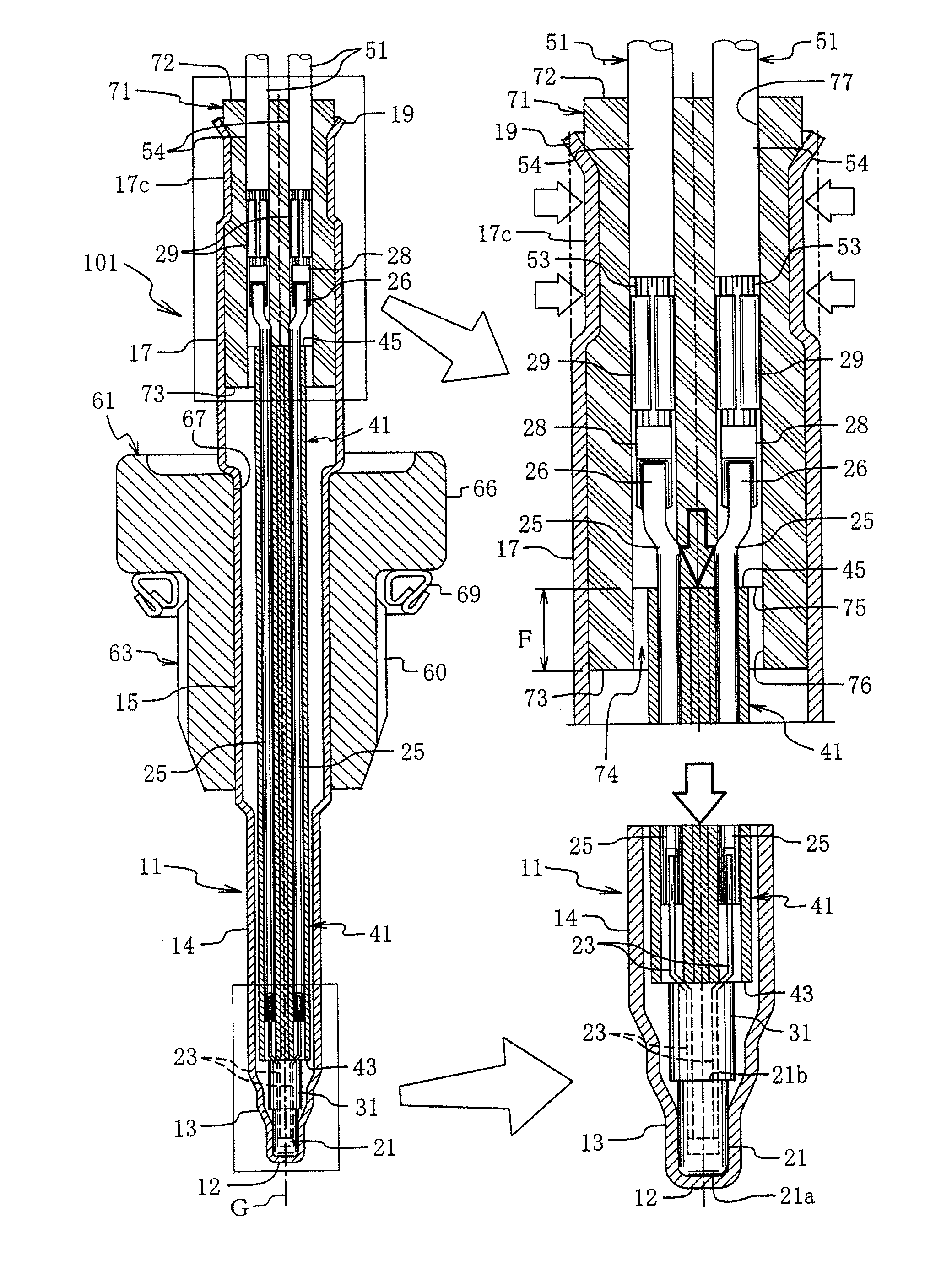
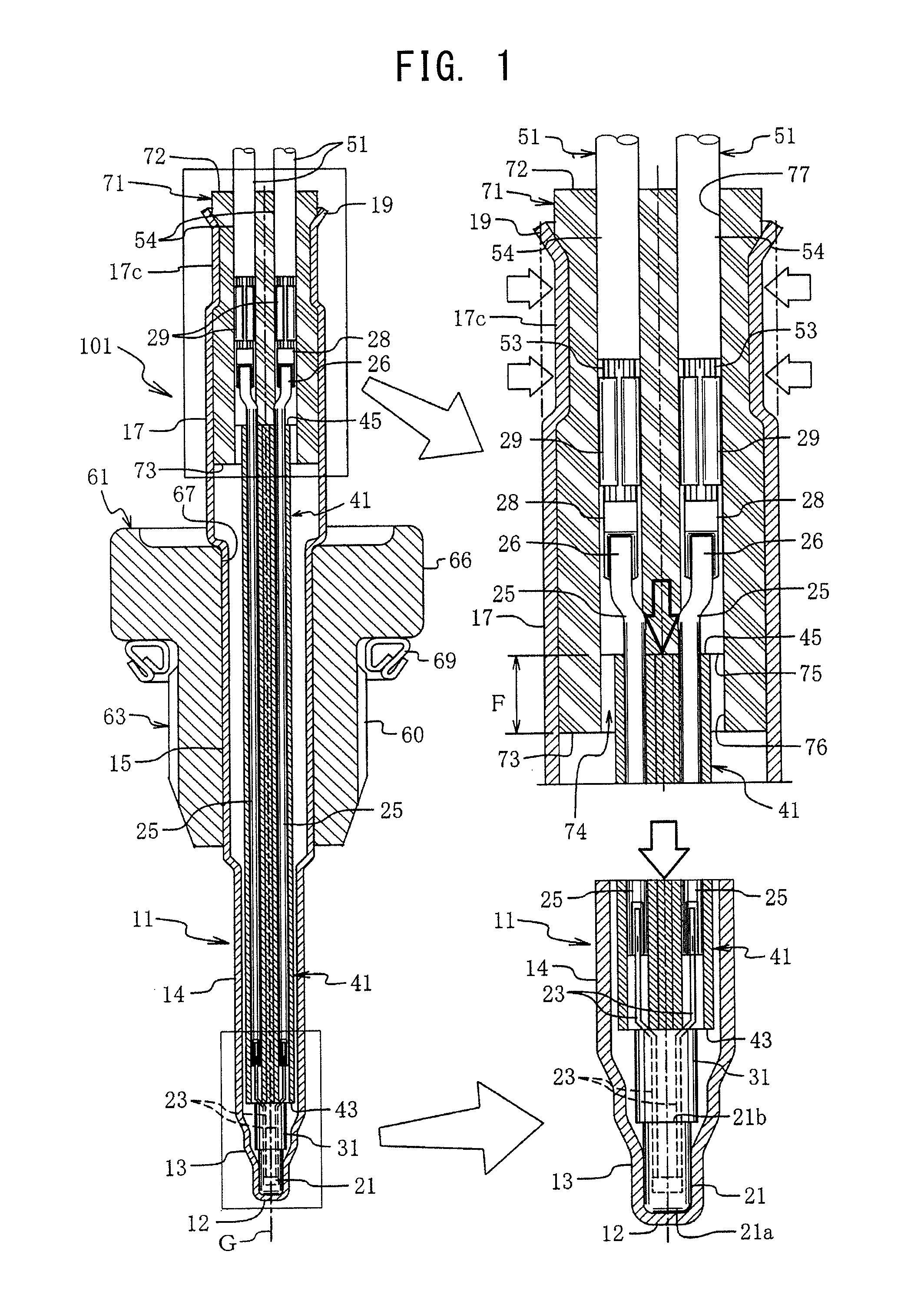
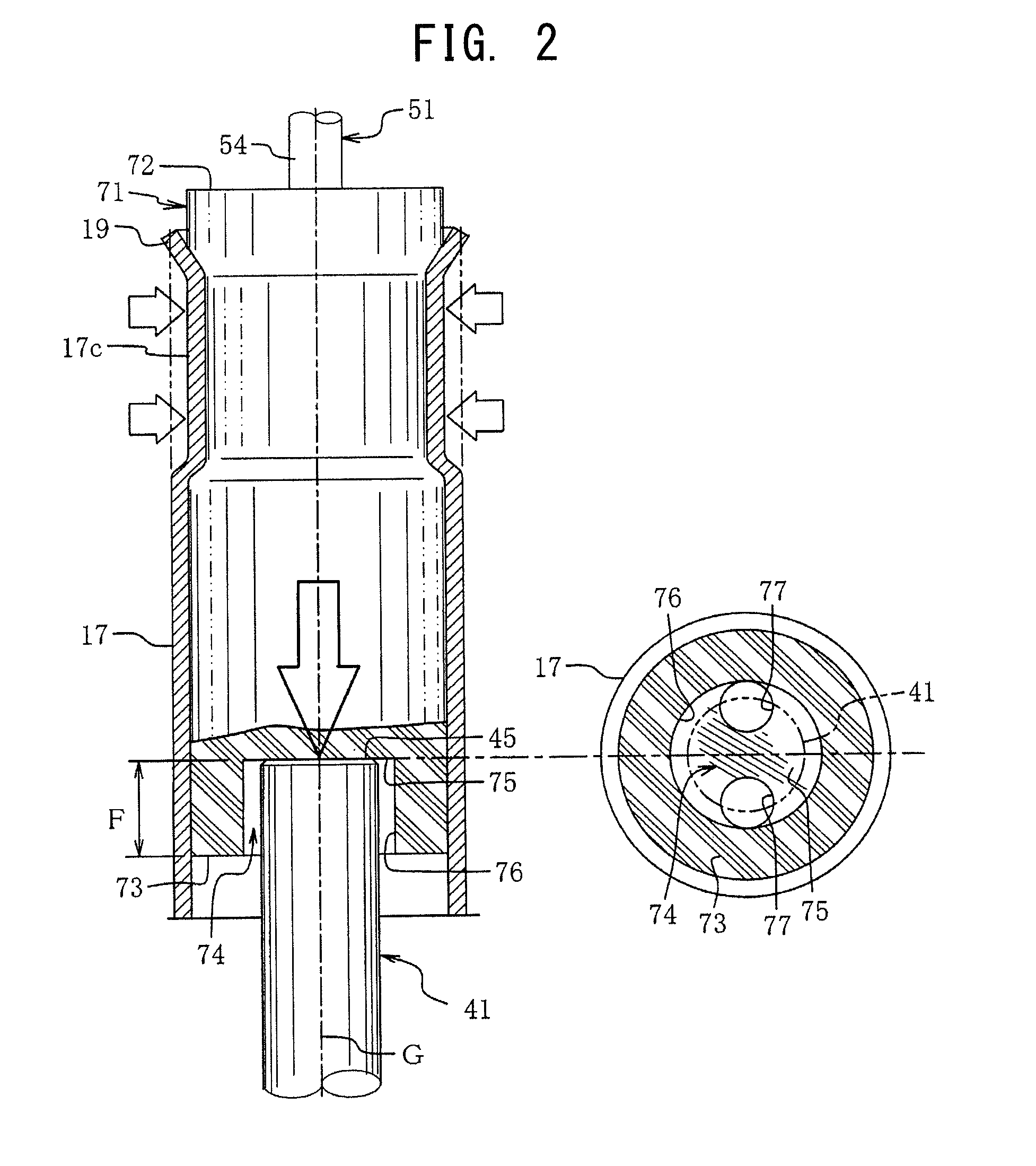
[0069]A temperature sensor according to an embodiment of the present invention will now be described in detail with reference to FIGS. 1 and 2. In FIG. 1, reference numeral 101 denotes a temperature sensor. The temperature sensor 101 includes a tube 11 made of metal (e.g., SUS) and having a closed front end 12; a temperature sensor element 21, which is disposed within the tube 11 such that the front end thereof is pressed against the front end 12 of the tube 11; an element support 31, which is an insulation member and is disposed rearward (upward in FIG. 1) of the element 21 within the tube 11 and through which electrode wires 23 extend rearward from the element 21; and an insulation sheath 41, which is a wiring insulator and is disposed rearward of the element support 31 and through which core wires 25 connected t...


PUM

PropertyMeasurementUnit
forceaaaaaaaaaa
diameteraaaaaaaaaa
diameteraaaaaaaaaa

Abstract

A sensor (101) is configured such that a seal member (71) is provided in a deformed manner through crimping of a portion of a tube (11) located toward a rear end (17c) of the tube (11). The seal member (71) is deformed such that a frontward-oriented surface (75), which is a bottom surface of a recess (74) formed in a front end (73) of the seal member (72), presses a rear end (45) of an insulation sheath (41) frontward. Consequently, a front end (21a) of a sensor element is pressed against a front end (12) of the tube (11) via the insulation sheath (41). By virtue of a pressing action induced by rubber-like elasticity, high sensor responsiveness is maintained over a long period of time.

Description

BACKGROUND OF THE INVENTION[0001]1. Field of the Invention[0002]The present invention relates to a temperature sensor for measuring the temperature of a fluid, such as exhaust gas from an engine. More particularly, the invention relates to a temperature sensor having a temperature sensor element, such as a thermistor, disposed in a front end portion of a metal tube having a closed front end (a closed-bottomed tube or cap), and which is attached to an exhaust manifold (an exhaust gas pipe) such that the front end of the tube is exposed to exhaust gas, and is favorably adapted to measure the temperature of the exhaust gas.[0003]2. Description of the Related Art[0004]Conventionally, a temperature sensor (hereinafter, also referred to as a sensor) of this type has been proposed as embodying various structures (refer to, for example, Patent Document 1). The temperature sensor disclosed in Patent Document 1 has the following structure: a temperature sensor element (hereinafter, also refer...

Claims


Application Information

Patent Timeline
Patent Type & Authority Patents(United States)
IPC IPC(8): G01K7/00G01K13/00G01K1/00
CPCG01K2013/024G01K1/08G01K13/02G01K2205/04G01K13/024
Inventor MATSUO, KOUJIISHIKAWA, SATOSHIITO, MASAMICHIMOGARI, SATOSHI
Owner NGK SPARK PLUG CO LTD
Why Eureka
Try Eureka