Subsea cable installation

a technology for installing subsea cables and cables, applied in the direction of cables, cables laying apparatus, service pipe systems, etc., can solve the problems of affecting the service life of the subsea cable, and causing the installation of multiple initially empty ducts to be difficult or delayed, and may not only be prohibitively expensiv

Active Publication Date: 2014-03-11
LEVEL 3 COMM LLC
View PDF22 Cites 10 Cited by
  • Summary
  • Abstract
  • Description
  • Claims
  • Application Information

AI Technical Summary

Benefits of technology

[0009]In a first aspect, the present invention provides a method of facilitating provision of a point to point cable connection between first and second points separated by an extended span, the method comprising providing multiple ducting from the first point through a first region of the extended span to a termination point intermediate the first and second points.

Problems solved by technology

Indeed, for an extended span, the provision of multiple initially empty ducts may not only be prohibitively expensive but counter productive as difficulties may be encountered in passing cables through such lengthy ducts.
The setting up of a cable connection often involves installation across a region presenting a particular difficulty or delay.
A particular problem with installing cable across a region of water is that usually the cable will have to be laid on the bed below the water.

Method used


Image

  • Subsea cable installation
  • Subsea cable installation
  • Subsea cable installation

Examples


Embodiment Construction

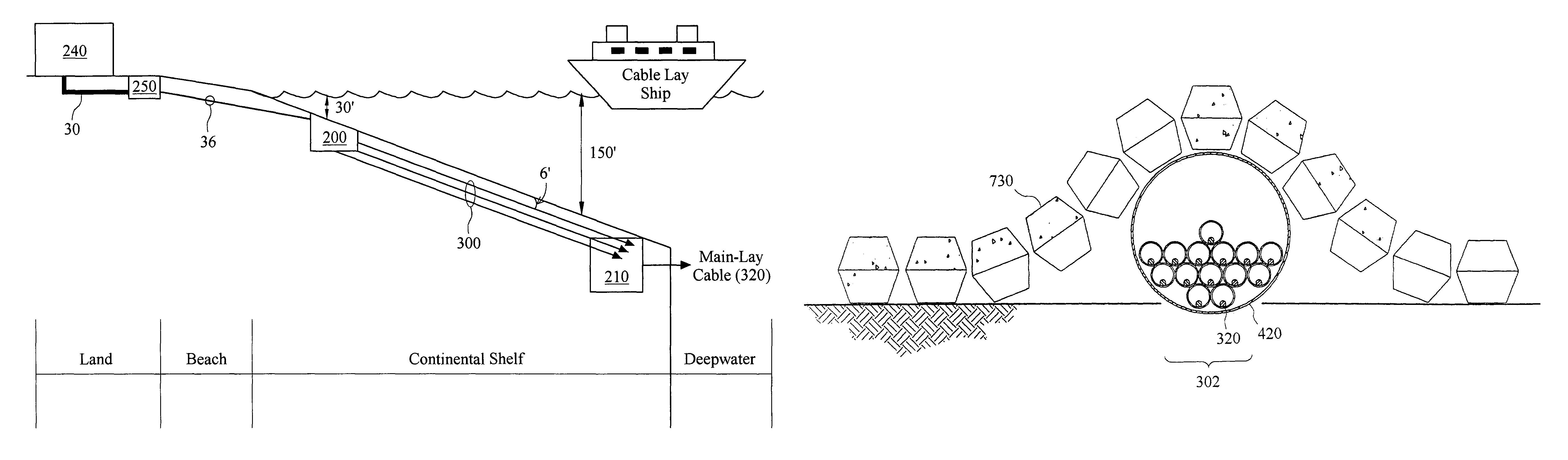
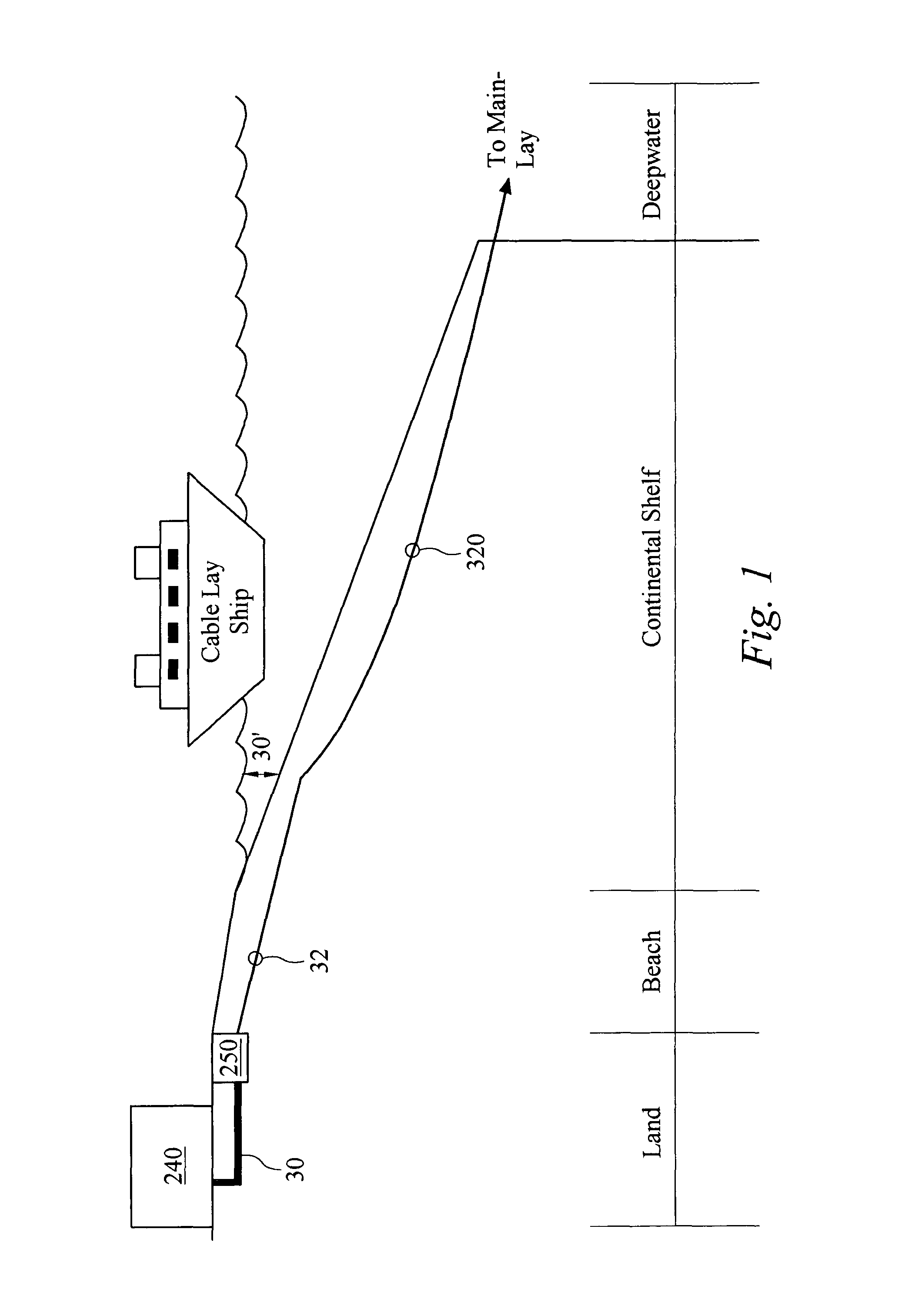
[0127]FIG. 1 is a diagram illustrating an arrangement for laying a sub-sea cable. Here, a conduit 30 is laid from a cable landing station 240 to a service site 250 at the beach front. From here, a single channel 32 is bored a certain distance out into the continental shelf, typically to a water depth of 30 feet. The cable 320 is drawn through this and is then laid on the shelf. The cable is armour-plated, typically double armoured and usually buried deeply in the shelf. At the end of the shelf, the cable is then laid across the ocean floor, often trenched, until the opposite continental shelf is met.

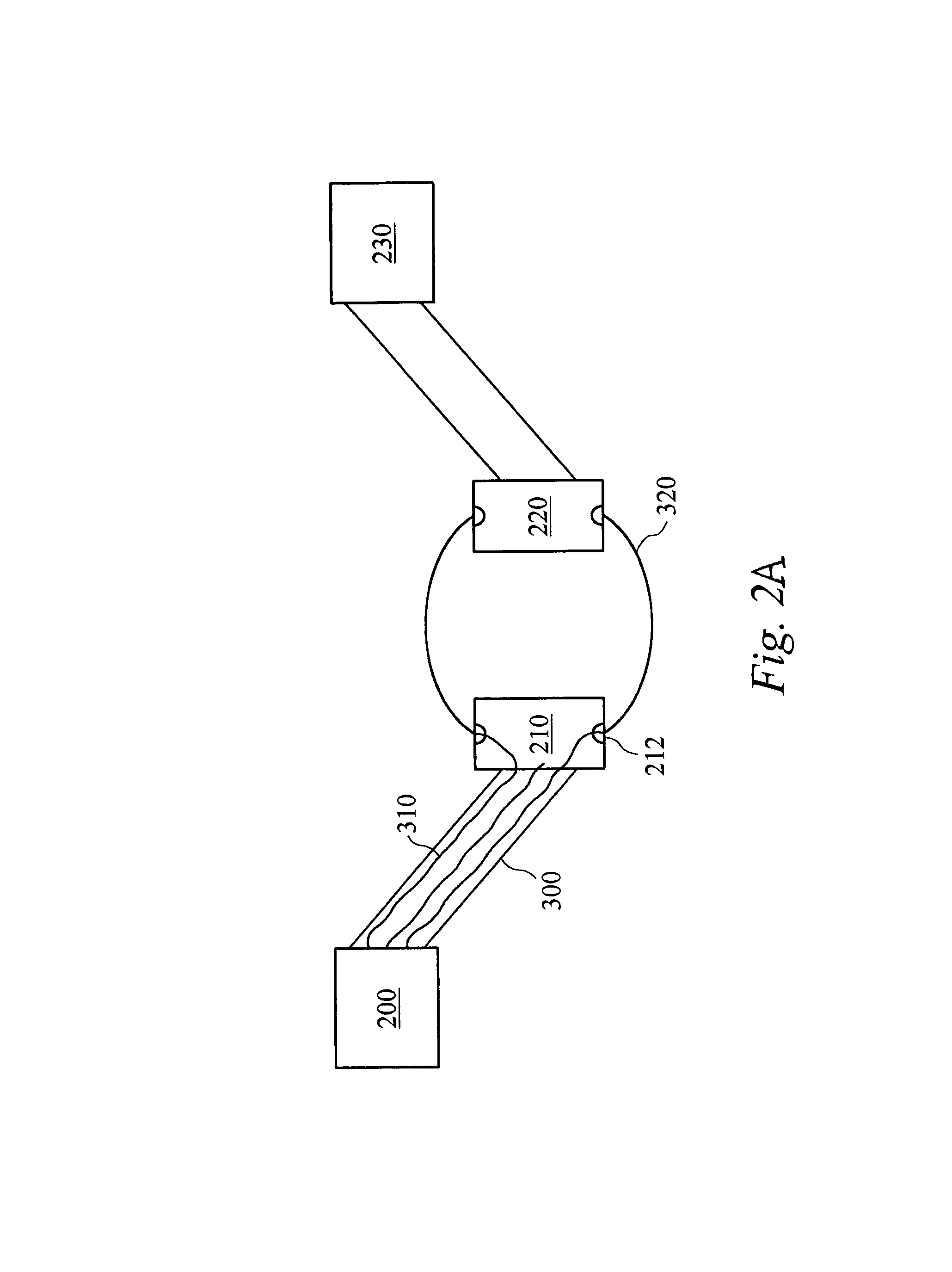
[0128]FIG. 2a is a diagram illustrating the arrangement of the sub-sea cable according to an embodiment of the invention. Multiple ducting 300 is laid from the junction point 200 to the termination point 210. The cables 310 split up in termination point 210 and exit the splice box or termination point 210 via cable exits 212 as armoured cables 320. The same apparatus is set up at the opp...


PUM


Abstract

The invention facilitates provision of a point-to-point cable connection between first and second points separated by an extended span of water including a first region of shallow water and a second region of relatively deep water. A plurality of ducts are provided from the first point through the first region of the extended span to an offshore termination point between the first and second points. Preferably, the ducts are buried in the seabed to prevent damage. At least one first cable is placed in one of the plurality of ducts to provide a connection between the first point and the offshore termination point. A second cable from the second point is received at the offshore termination point. The first cable is connected to the second cable at the offshore termination point to create the point-to-point cable connection. In one embodiment, the offshore termination point is located on the continental shelf near the transition to deep water. Cable can be installed between the first point and the offshore termination point with relative ease by passing the cable through an available conduit. This eliminates the need for the time consuming and expensive permitting process typically associated with near-shore cable installation.

Description

CROSS-REFERENCE TO RELATED APPLICATIONS[0001]This application claims priority to U.S. Provisional Application No. 60 / 252,130, filed Nov. 21, 2000, the full text of which is incorporated herein by reference.BACKGROUND OF THE INVENTION[0002]1. Field of the Invention[0003]The present invention relates to the installation of cables. The invention is primarily concerned with fibre optic communication cables but may be applied to other cables, for example co-axial or other communication or power cables. The invention is particularly concerned with providing a cable connection over an extended span, particularly over a sea or other water crossing and in a preferred application is concerned with providing a deep sea (for example transatlantic) cable crossing; however, aspects of the invention may be applied to land based or other applications.[0004]2. Background Art[0005]There are a variety of known techniques for laying cables, whether sub-sea or otherwise, each of which has associated pro...

Claims


Application Information

Patent Timeline
Patent Type & Authority Patents(United States)
IPC IPC(8): F16L1/12H02G15/14G02B6/50H02G1/10F16L1/16
CPCH02G1/10F16L1/123H02G15/14G02B6/506
Inventor VIDAL, RONALD J.ALEXANDER, PAULKELLY, ROBERT M.BRUTON, DAVIDTODD, ROBERT
Owner LEVEL 3 COMM LLC
Why Eureka
Try Eureka