Drop-floor trailer

a trailer and floor technology, applied in the field of trailers, to achieve the effect of simple construction and use, and low manufacturing cos

Inactive Publication Date: 2014-03-11
BARON BEN
View PDF10 Cites 2 Cited by
  • Summary
  • Abstract
  • Description
  • Claims
  • Application Information

AI Technical Summary

Benefits of technology

[0010]Thus, it can be seen that since the drop floor is freely suspended from the articulated mechanism, it does not perceive any load except for its own weight and the weight of the cargo. The structure is simple in construction and use and is inexpensive to manufacture.

Problems solved by technology

A common disadvantage of both known trailers is that the drop floor per se functions as a closing part of the articulated linkage mechanism and therefore, in addition to the weight of the cargo, experiences a part of the load caused by the floor lifting-dropping force.

Method used


Image

  • Drop-floor trailer
  • Drop-floor trailer
  • Drop-floor trailer

Examples


Embodiment Construction

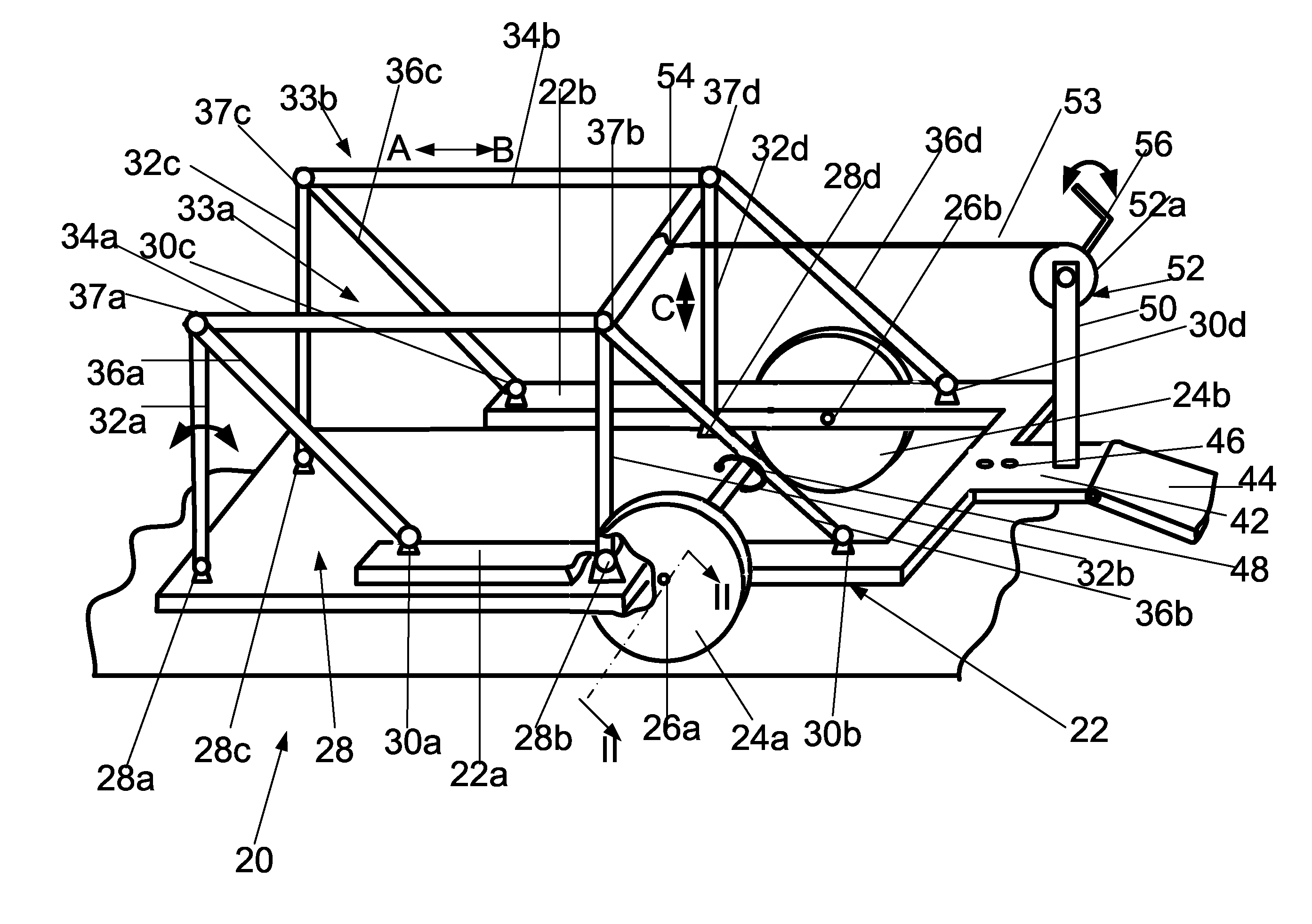
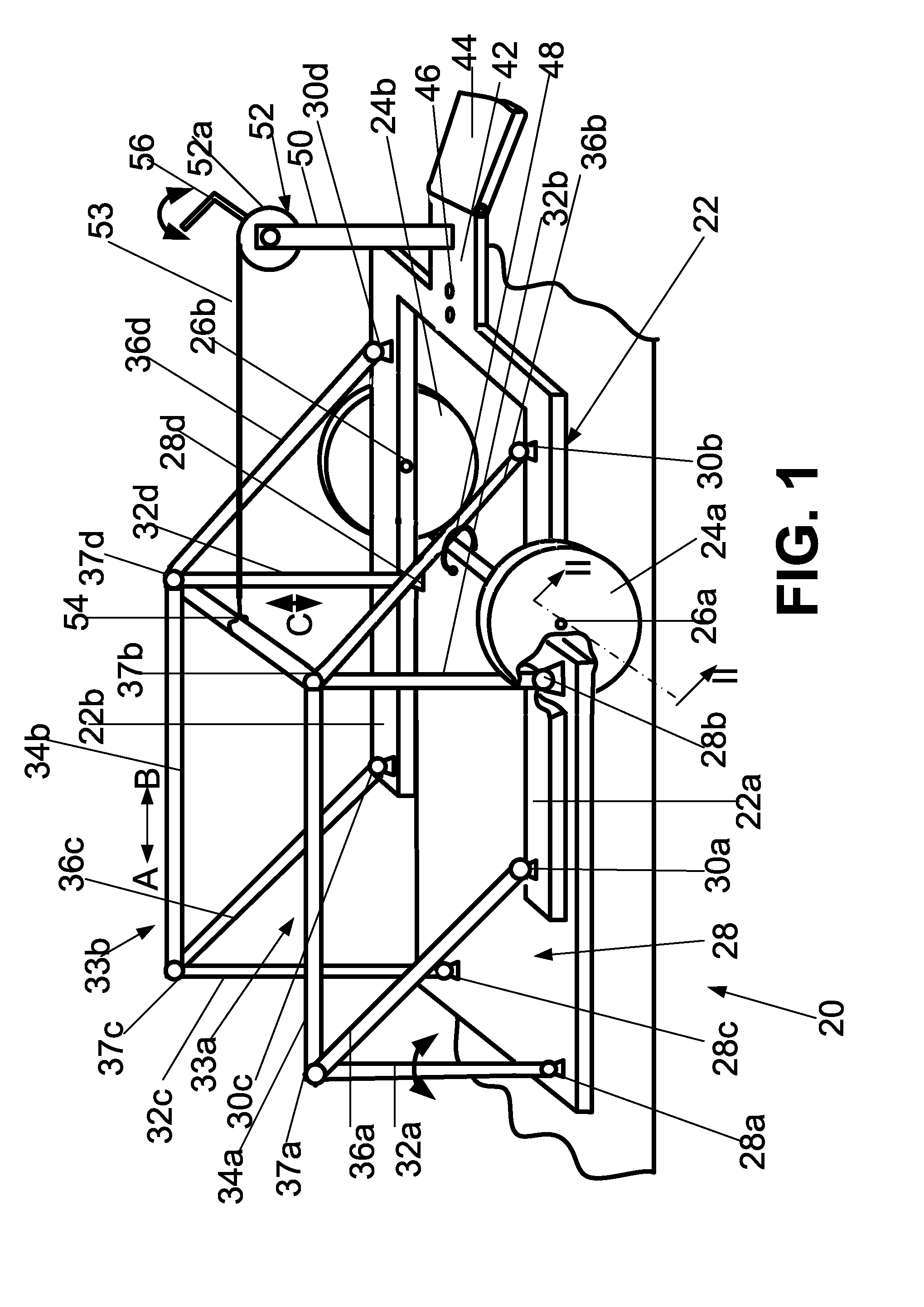
[0017]A flat drop-floor trailer of the present invention (hereinafter referred to as a “drop-floor trailer”), which as a whole is designated by reference numeral 20, is shown in FIG. 1, which is a schematic three-dimensional view of the drop-floor trailer. As shown in FIG. 1, the drop-floor trailer 20 has a U-shaped frame 22 that is supported by at least two wheels 24a and 24b rotationally installed on independent axles 26a and 26b in side members 22a and 22b of the U-shaped frame 22 so that the space of the frame between the side members 22a and 22b of the U-shaped configuration remains unobstructed for placing the flat drop floor 28 in that space.

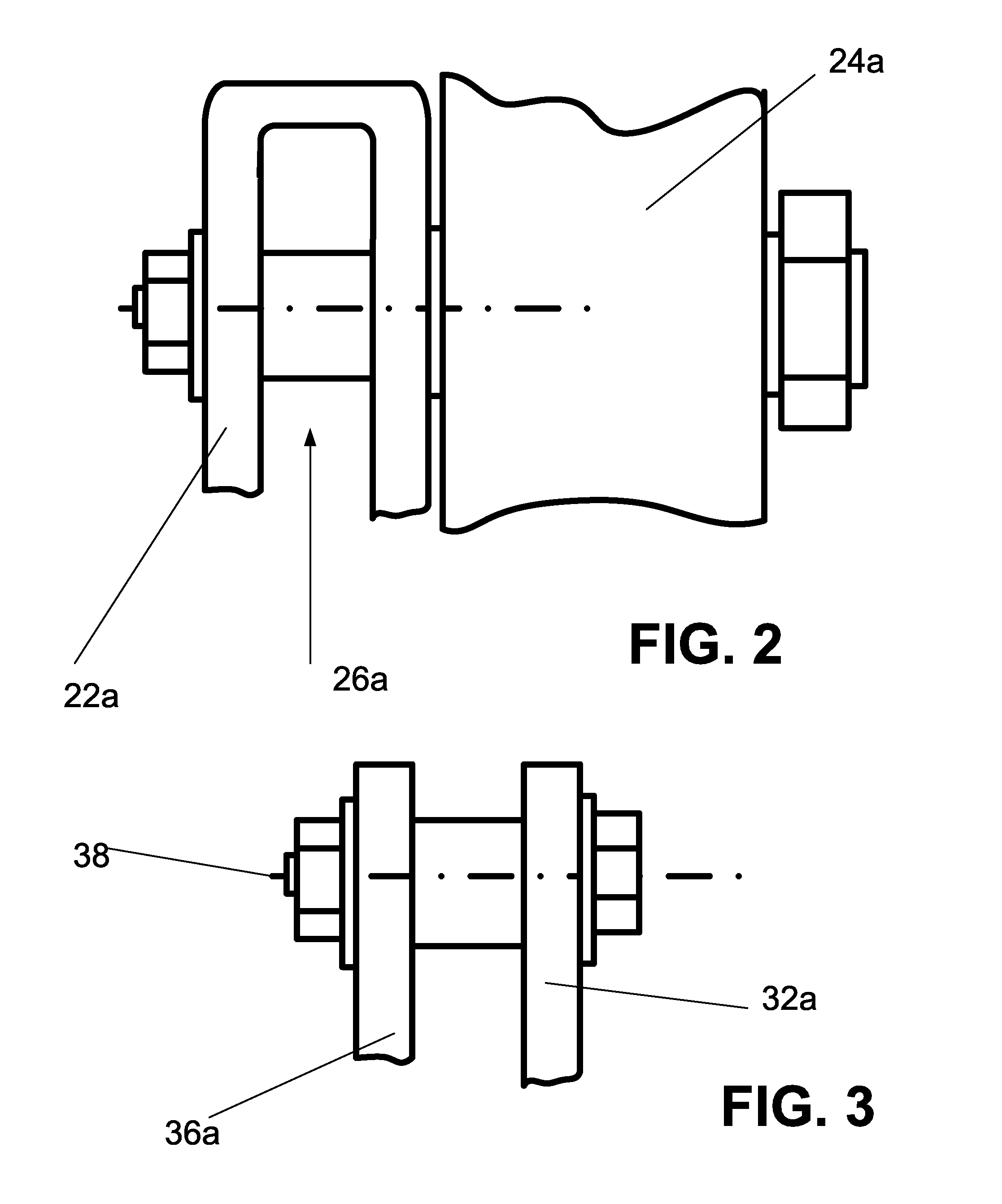
[0018]Each side member 22a and 22b of the U-shaped frame 22 pivotally supports vertical struts 32a, 32b, 32c, and 32d by pivots 30a, 30b, 30c, and 30d. The upper ends of the struts are interconnected by respective horizontal bars 34a and 34b that are pivotally linked to said upper ends of the struts.

[0019]As a result, on each side of the ...


PUM


Abstract

Proposed is a wheeled drop-floor trailer that has a U-shaped frame with two articulated linkages pivotally installed on the sides of the U-shaped frame and suspension rods that pivotally support the drop floor in a freely hanging condition. On the side of the trailer opposite the loading side the articulated linkages are interconnected by a cross bar, which is connected to a drive mechanism, e.g., to a winch, via a cable. When the articulated linkages are inclined toward the loading side, the drop floor descends to the ground under its own weight and, after the cargo is loaded onto the drop floor, the latter is raised by pulling the linkages with the use of the winch via the cable and the cross bar in the direction opposite the loading side.

Description

FIELD OF THE INVENTION[0001]The present invention relates to trailers, more particularly to a drop-floor trailer having a flat bed or floor that is oriented horizontally and can be lowered to ground level for loading equipment, such as a motorcycle, a small vehicle, a container, etc., and then can be raised to an upper position that provides clearance over the ground sufficient for towing trailed cargo by a drive vehicle.[0002]For example, among a great variety of other flatbed trailers are roof-free flatbed trailers, which are known in the art, employing an articulated linkage mechanism for lowering a flatbed, which is also known as a carrier bed, or drop floor, to the ground for loading cargo to the horizontally oriented drop floor without the use of a tilted ramp and for subsequent lifting of the drop floor with the cargo to the level sufficient for hauling the loaded trailer by a vehicle to which it is hitched. In the trailer of such a type, the drop floor typically remains para...

Claims


Application Information

Patent Timeline
Patent Type & Authority Patents(United States)
IPC IPC(8): B60P3/00
CPCB60P1/025B60P3/122B60P3/00
Inventor BARON, BEN
Owner BARON BEN
Why Eureka
Try Eureka