Turbine nozzles and methods of manufacturing the same

a technology of turbine engines and nozzles, applied in the direction of liquid fuel engines, forging/pressing/hammering apparatus, lighting and heating apparatus, etc., can solve the problems of reducing the cooling of the combustor, and affecting the cooling effect of the combustor

Inactive Publication Date: 2014-03-11
HONEYWELL INT INC
View PDF18 Cites 18 Cited by
  • Summary
  • Abstract
  • Description
  • Claims
  • Application Information

AI Technical Summary

Problems solved by technology

In particular, in configurations in which the inner and outer rings of the turbine nozzle comprise numerous segments, gas leakage may occur at interfaces between adjacent segments.
As a result, a chargeable cooling flow may be unintentionally added to the gas flowing through the turbine nozzle, which may cause the turbine engine to increase fuel consumption.
In some instances, leakage between the adjacent segments may result in decreased combustor cooling.
Though bi-cast inner and outer rings reduce leakage of turbine nozzles, they may be relatively difficult and / or time consuming to manufacture.
Additionally, coatings, such as thermal barrier layers, may be relatively difficult to apply to bi-cast turbine nozzles.
In particular, because of limitations with deposition apparatus and processes for forming thermal barrier layers, formation of the thermal barrier layers on the stationary vanes may be a relatively complex process.
In addition, bi-cast or brazed full ring turbine nozzles suffer from thermo-mechanical fatigue (TMF) due to the thermo-mechanical stresses that develop between the vanes and the inner ring and between the vanes and the outer ring.

Method used


Image

  • Turbine nozzles and methods of manufacturing the same
  • Turbine nozzles and methods of manufacturing the same
  • Turbine nozzles and methods of manufacturing the same

Examples


Embodiment Construction

[0024]The following detailed description is merely exemplary in nature and is not intended to limit the inventive subject matter or the application and uses of the inventive subject matter. Furthermore, there is no intention to be bound by any theory presented in the preceding background or the following detailed description.

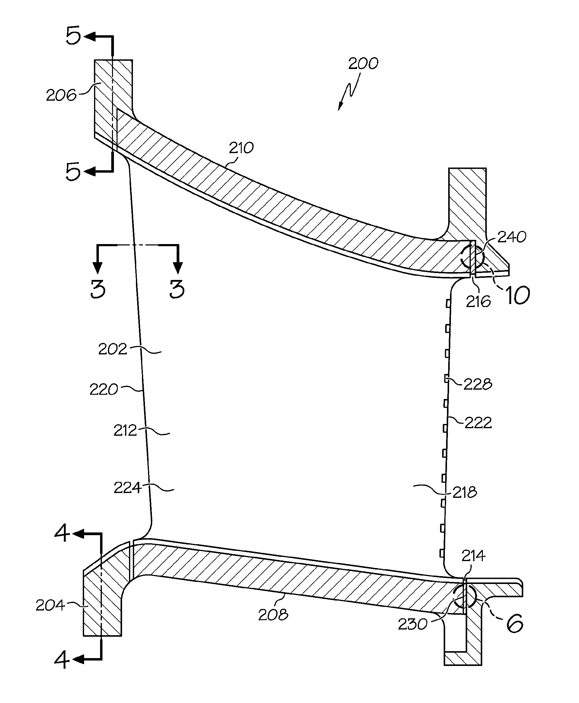
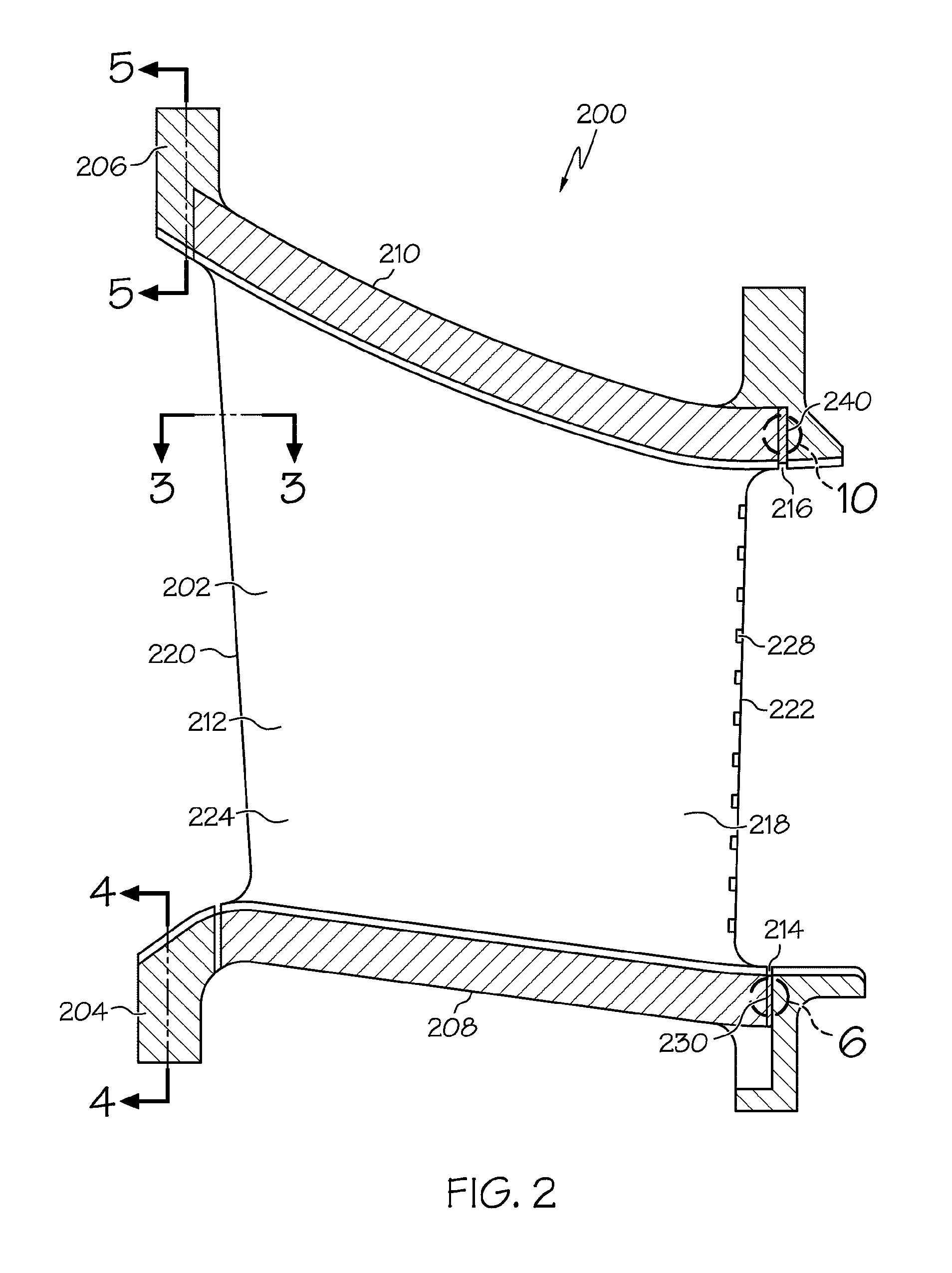
[0025]Generally, the inventive subject matter relates to improved turbine nozzles having at least a first ring having a first microstructure, a vane extending from the first ring, and a porous zone between the first ring and the vane that is more porous than the first microstructure. The porous zone can include a macroporous region, in an embodiment. In another embodiment, the porous zone can include a microporous region. In any case, inclusion of the porous zone is intended to attenuate thermo-mechanical fatigue cracking between the vane and the first ring by serving as a low stress compliant joint.

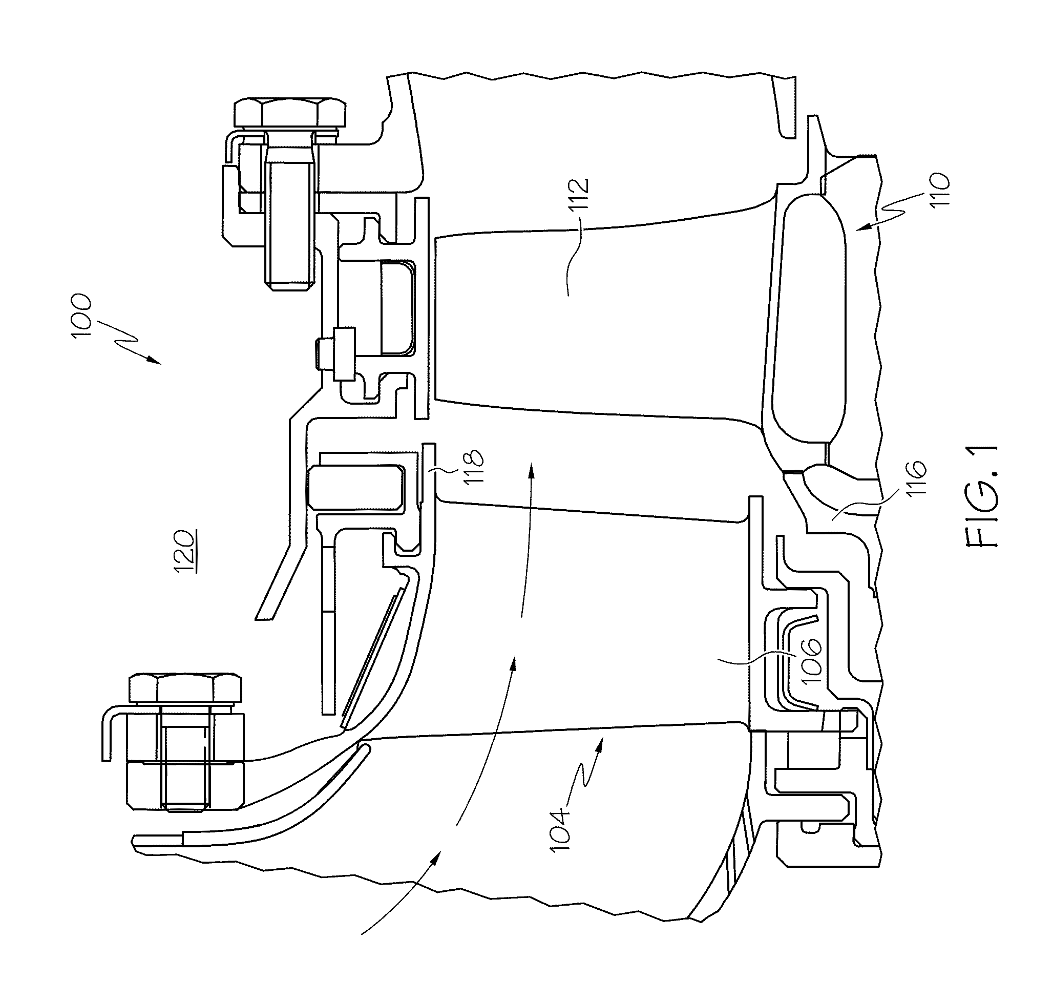
[0026]An example of a system including the turbine nozzle is de...


PUM

PropertyMeasurementUnit
temperatureaaaaaaaaaa
diameteraaaaaaaaaa
diameteraaaaaaaaaa

Abstract

A turbine nozzle is provided and includes a first ring having a first microstructure, a vane extending from the first ring, a first porous zone between the first ring and the vane that is more porous than the first microstructure to attenuate thermo-mechanical fatigue cracking between the vane and the first ring. Methods of manufacturing the turbine nozzle are also provided.

Description

TECHNICAL FIELD[0001]The inventive subject matter generally relates to turbine engine components, and more particularly relates to turbine nozzles and methods of manufacturing turbine nozzles.BACKGROUND[0002]Gas turbine engines may be used to power various types of vehicles and systems, such as air or land-based vehicles. In typical gas turbine engines, compressed air generated by axial and / or radial compressors is mixed with fuel and burned, and the expanding hot combustion gases are directed along a flowpath and through a turbine nozzle having stationary turbine vanes. The gas flow deflects off of the vanes and impinges upon turbine blades of a turbine rotor. A rotatable turbine disk or wheel, from which the turbine blades extend, spins at high speeds to produce power. Gas turbine engines used in aircraft use the power to draw more air into the engine and to pass high velocity combustion gas out of the gas turbine aft end to produce a forward thrust. Other gas turbine engines may ...

Claims


Application Information

Patent Timeline
Patent Type & Authority Patents(United States)
IPC IPC(8): F01D9/02
CPCF05D2260/94F05D2260/941B23P15/04F01D25/28F01D9/041Y02T50/67B33Y80/00Y10T29/4932Y02T50/60
Inventor MORRIS, MARK C.RYAN, DANIELGODFREY, DONALD G.SMOKE, JASON
Owner HONEYWELL INT INC
Why Eureka
Try Eureka