Free fall simulator

a simulator and free fall technology, applied in the field of free fall simulators, can solve the problems of heat in the simulator affecting the safety of people, etc., and achieve the effect of reducing the temperature in the interior and low cost expenditur

Inactive Publication Date: 2014-03-11
INDOOR SKYDIVING BOTTROP
View PDF12 Cites 9 Cited by
  • Summary
  • Abstract
  • Description
  • Claims
  • Application Information

AI Technical Summary

Benefits of technology

[0009]The present invention is based on the task of proposing a free fall simulator and an aeration device for a wind tunnel, in particular a free fall simulator, wherein the temperature in the interior is to be reduced effectively and at low cost expenditure. This task is solved by a free fall simulator according to the claims of the present application and an aeration device according to the claims of the present application.

Problems solved by technology

A typical effect of these so-called closed-type free fall simulators is that, due to pressure losses, the air within the simulator is heated which entails various problems.
On the one hand, the overheating of the air may be perceived as unpleasant by the persons using the simulator, or in case of a considerable overheating, may even be injurious to health.
On the other hand, the heating of the air results in a reduction of the air density which in turn decreases the force keeping the hovering person in equilibrium.
In total, an increased control expenditure is necessary due to the combination of fans frequently arranged next to each other and the aerating means which can be opened as required.
Such a temperature regulation is associated with a limited material choice and complicated.
This leads to increased energy consumption which, together with the manufacturing costs for the extractor fans, requires considerable additional financial expenditures.
A disadvantage of this free fall simulator is that due to the constriction of the flow cross-section by the inlet door and outlet door, the flow speed is further increased in the area of these doors resulting in increased air friction with additional heat generation.
Moreover, the inlet and outlet doors are exposed to extremely high stress due to their orientation into the air stream.

Method used


Image

  • Free fall simulator
  • Free fall simulator
  • Free fall simulator

Examples


Embodiment Construction

[0049]Certain terminology is used in the following description for convenience only and is not limiting. The words “lower,”“bottom,”“upper” and “top” designate directions in the drawings to which reference is made. The words “inwardly” and “outwardly” refer to directions toward and away from, respectively, the geometric center of the device, and designated parts thereof, in accordance with the present invention. Unless specifically set forth herein, the terms “a,”“an” and “the” are not limited to one element, but instead should be read as meaning “at least one.” The terminology includes the words noted above, derivatives thereof and words of similar import.

[0050]In the following description, the same reference numerals will be used for equal components or components of equal effect.

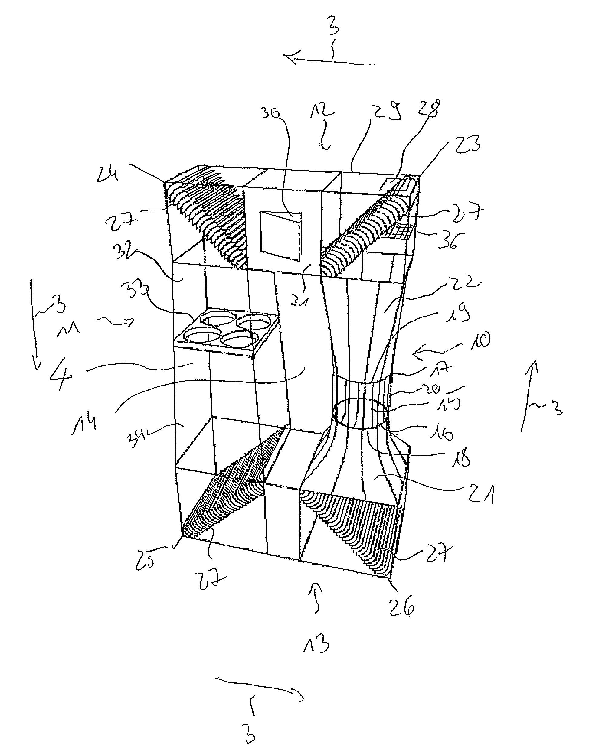
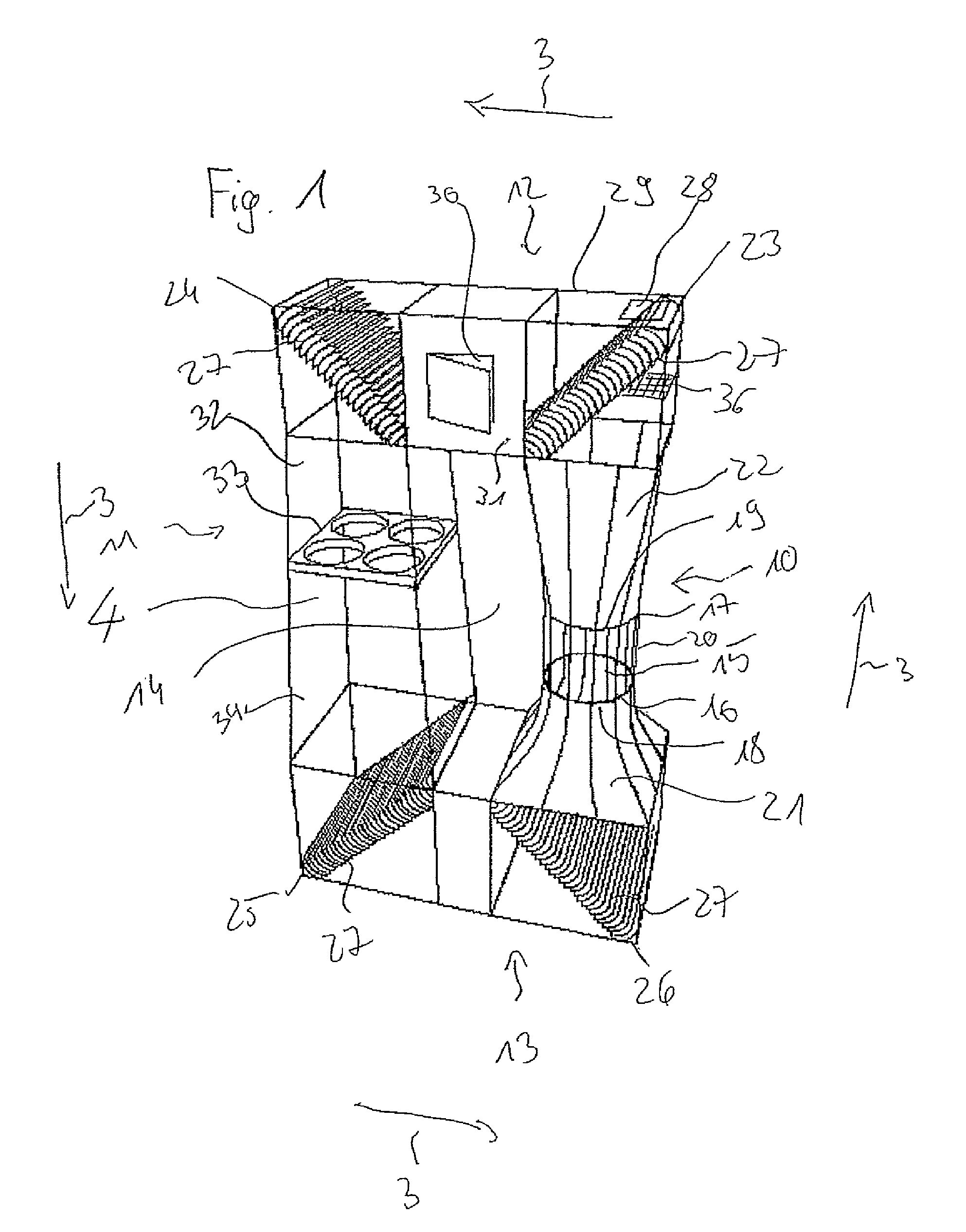
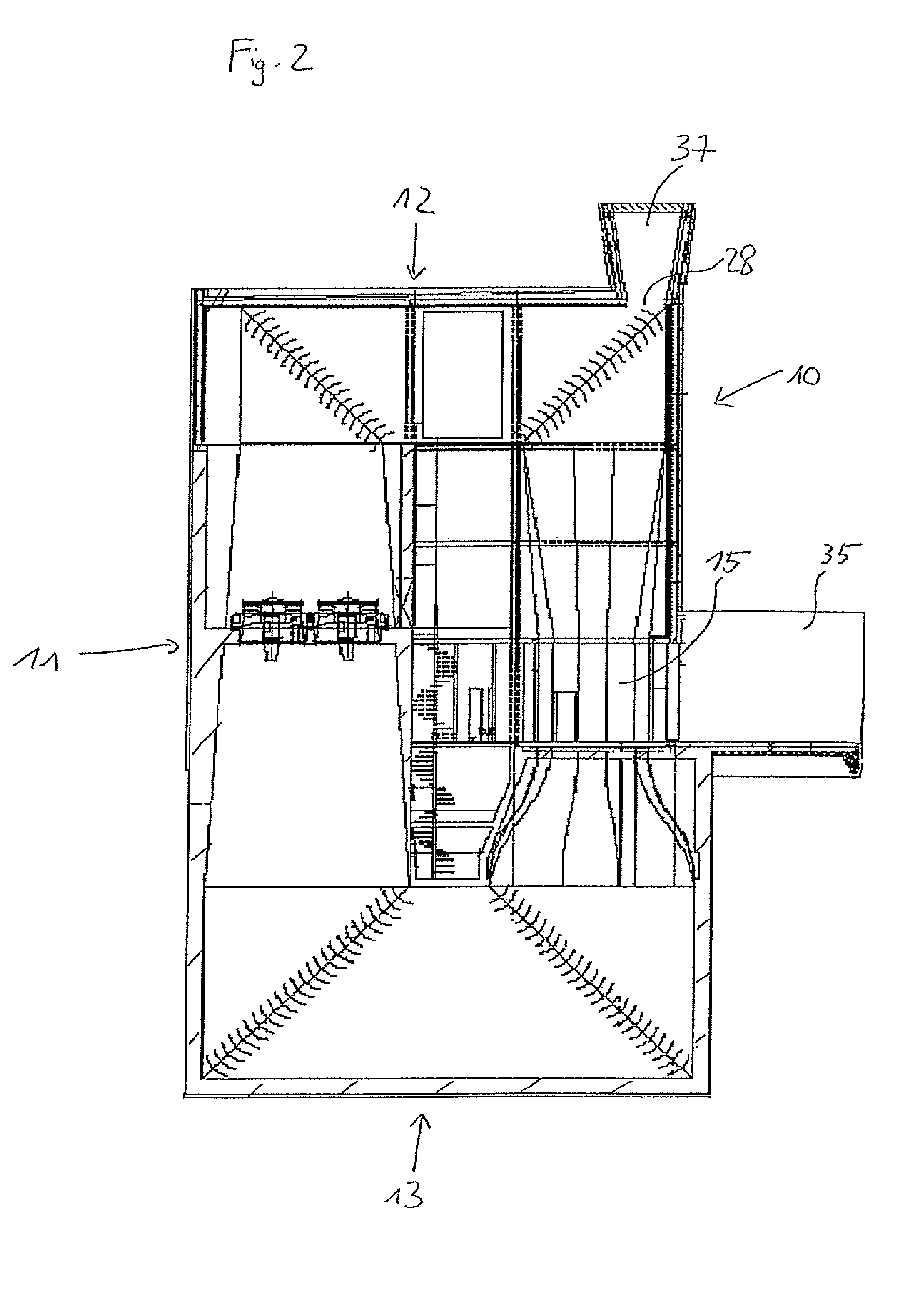
[0051]FIG. 1 shows a free fall simulator having a self-contained air circuit, including a first and second vertical section 10, 11 and a first and second horizontal section 12, 13. The two vertical sectio...


PUM


Abstract

A free fall simulator includes a self-contained air circuit and a hover chamber in which persons can hover as a result of an air stream directed vertically upward. A lower opening is located at a lower end of the hover chamber and an upper opening is located at an upper end of the hover chamber. A substantially closed air guide channel includes at least one fan. The channel connects the lower opening and the upper opening of the hover chamber. At least one air inlet opening and at least one air outlet opening allow for exchanging air within the air guide channel. The simulator includes redirecting lamellae which redirect an air stream within the air guide channel in corner areas or areas of high curvature, wherein at least one air outlet opening is disposed within the redirecting lamellae.

Description

CROSS-REFERENCE TO RELATED APPLICATIONS[0001]This application is a Section 371 of International Application No. PCT / EP2009 / 061251, filed Sep. 1, 2009, which was published in the German language on Mar. 18, 2010, under International Publication No. WO 2010 / 028980 A1 and the disclosure of which is incorporated herein by reference.BACKGROUND OF THE INVENTION[0002]The present invention relates to a free fall simulator including a self-contained air circuit and an aeration device for a wind tunnel, in particular a free fall simulator.[0003]A free fall simulator including a self-contained air circuit is an apparatus adapted to maintain a person in a hovering position in a (as a rule controllable) vertically ascending air stream which flows through a hover chamber. After exiting an upper opening of the hover chamber, the air stream is redirected to a lower opening of the hover chamber via an air guide channel in such a manner that a self-contained air circuit is formed.[0004]A typical effe...

Claims


Application Information

Patent Timeline
Patent Type & Authority Patents(United States)
IPC IPC(8): G09B9/08
CPCA63G31/00B64D23/00A63G2031/002A63G2031/005
Inventor NEBE, BORISDOHR, MANUEL
Owner INDOOR SKYDIVING BOTTROP
Why Eureka
Try Eureka