Lubrication structure of differential gear unit

a technology of differential gear unit and lubrication structure, which is applied in the direction of screws, load-modified fasteners, and screws, etc., can solve the problems of abnormal noise produced by the head of the bolt against the guide rib, and achieve the effect of suppressing the noise, increasing the rotational resistance and increasing the manufacturing cost of the differential gear uni

Active Publication Date: 2014-03-11
TOYOTA JIDOSHA KK
View PDF10 Cites 18 Cited by
  • Summary
  • Abstract
  • Description
  • Claims
  • Application Information

AI Technical Summary

Benefits of technology

[0014]According to this lubrication structure of a differential gear unit described above, the case has the guide rib that extends over a certain area with respect to the rotation path of the head of the bolt when the ring gear rotates, and that protrudes out from the case toward the head of the bolt. As a result, if the clamping force of the bolt gradually loosens, the head of the bolt will contact the guide rib. Thus, the clamping force of the bolt can be maintained.
[0016]Further, the through-hole that extends in the vertical direction is provided in an upper portion of the hollow supporting portion, and the guide rib has the guide portion positioned above the through-hole with respect to the rotation path of the head of the bolt. As a result, oil that drips from above the case down onto the differential gear unit can be led from the guide portion to the bearing through the through-hole, such that the bearing can be lubricated.
[0017]Thus, the guide rib that maintains the clamping force of the bolt is also able to serve as a guide rib for lubricating the bearing. Hence, there is no need to raise the oil level to immerse the tapered roller bearing in oil, as there is with the related art. As a result, it is possible to suppress an increase in the rotational resistance of the differential gear unit, as well as suppress an increase in the manufacturing cost of the differential gear unit.
[0019]According to the lubrication structure of a differential gear unit described above, the guide rib that extends from the case toward the head of the bolt for a length of 80° to 100° inclusive is provided, which simultaneously inhibits approximately one-quarter of all of the bolts that fasten the ring gear to the differential case along the entire circumference from loosening. As a result, all of the bolts can be inhibited from loosening by the ring gear and the differential case rotating. Also, oil that drips down onto the differential gear unit from above the case can be led from the guide portion to the bearing through the through-hole, so that the bearing can be lubricated.
[0023]With this lubrication structure of a differential gear unit, the guide portion has the auxiliary guide rib that extends upward from a portion of the guide rib positioned above the upper end opening of the through-hole, and that receives oil drawn up by the ring gear, and this auxiliary guide rib is positioned on the downstream side, in the direction of forward rotation of the ring gear, of the upper end opening of the through-hole. Therefore, oil that strikes the auxiliary guide rib during forward rotation, i.e., the rotational direction that is normally used, runs down along the auxiliary guide rib and is thus able to be guided to the upper end opening of the through-hole. Accordingly, the oil can be supplied to the bearing through the through-hole, so the bearing can be lubricated using the guide rib that maintains the clamping force of the bolt.
[0024]Accordingly, the invention is able to provide a lubrication structure of a differential gear unit in which a guide rib that maintains the clamping force of a bolt is also able to serve as a guide rib for lubricating a bearing, which enables an increase in rotational resistance of the differential gear unit, as well as an increase in the manufacturing cost of the differential gear unit, to be suppressed.

Problems solved by technology

Also, contact by the head of the bolt against the guide rib produces an abnormal noise.

Method used


Image

  • Lubrication structure of differential gear unit
  • Lubrication structure of differential gear unit
  • Lubrication structure of differential gear unit

Examples


Embodiment Construction

[0034]Hereinafter, example embodiments of the lubrication structure of a differential gear unit according to the invention will be described with reference to the accompanying drawings. First, a first example embodiment will be described. FIGS. 1 to 5 are views of the first example embodiment of the lubrication structure of a differential gear unit according to the invention. Incidentally, in this example embodiment, the lubrication structure of a differential gear unit is described as being applied to a hybrid vehicle.

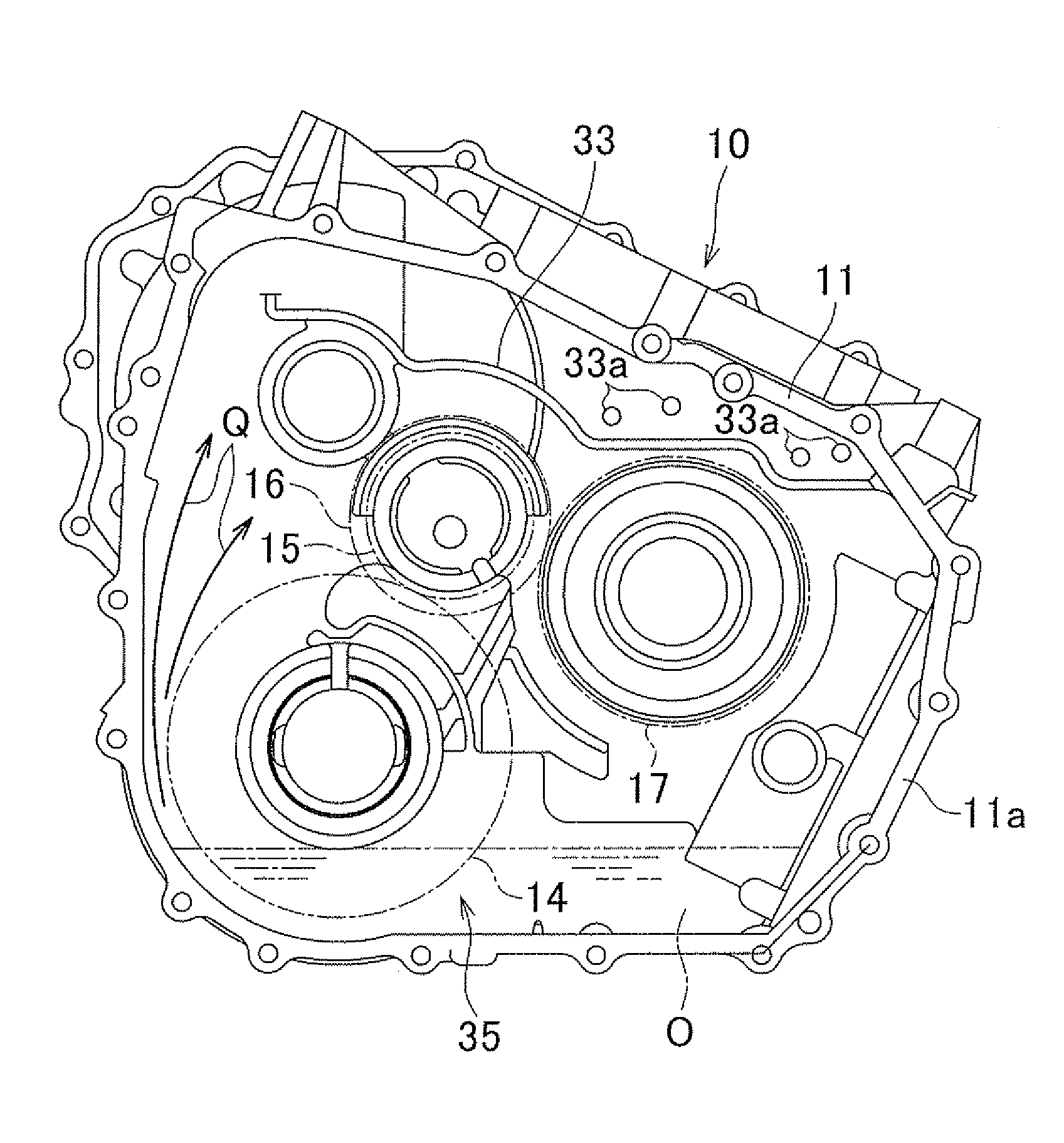
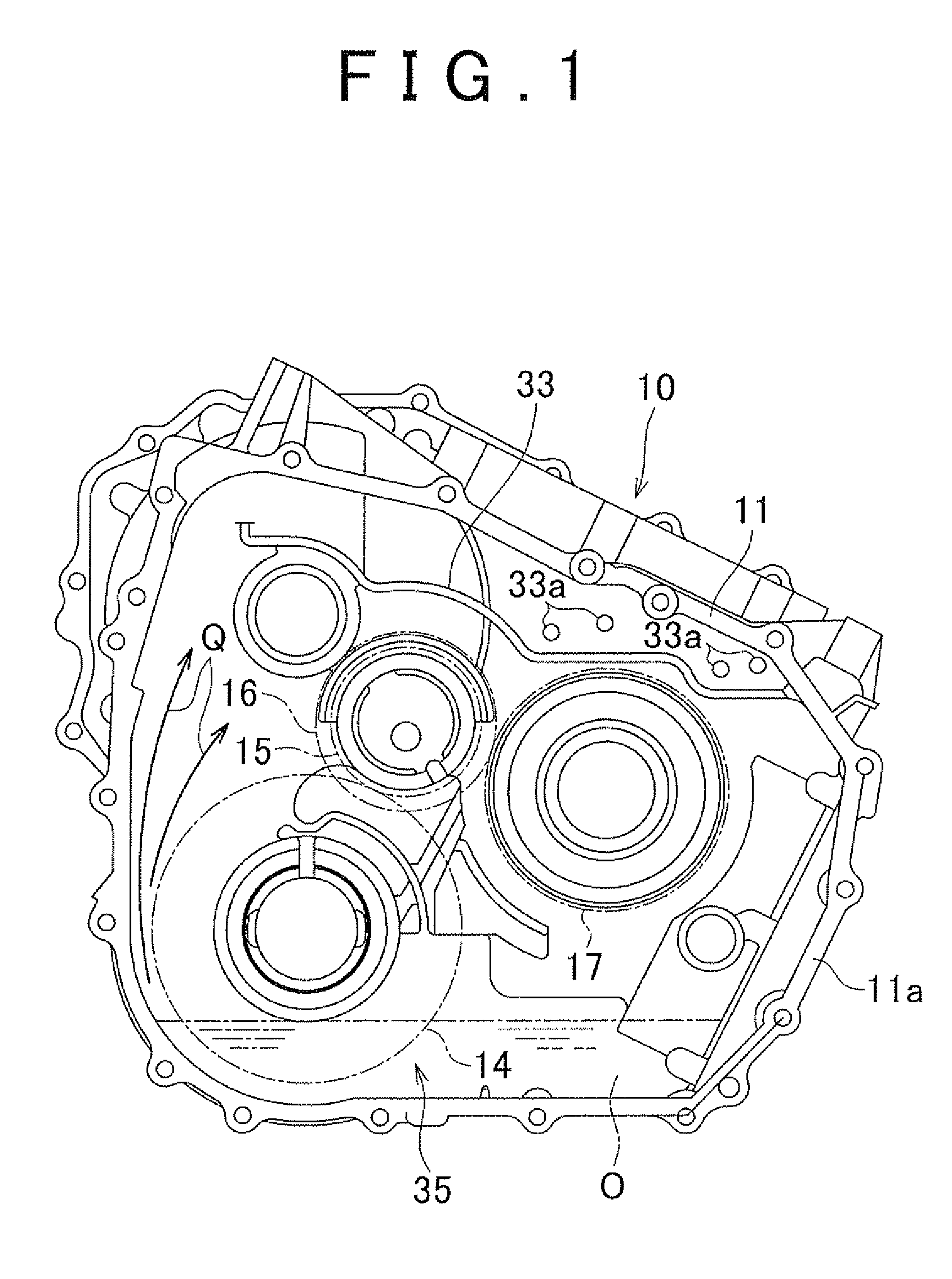
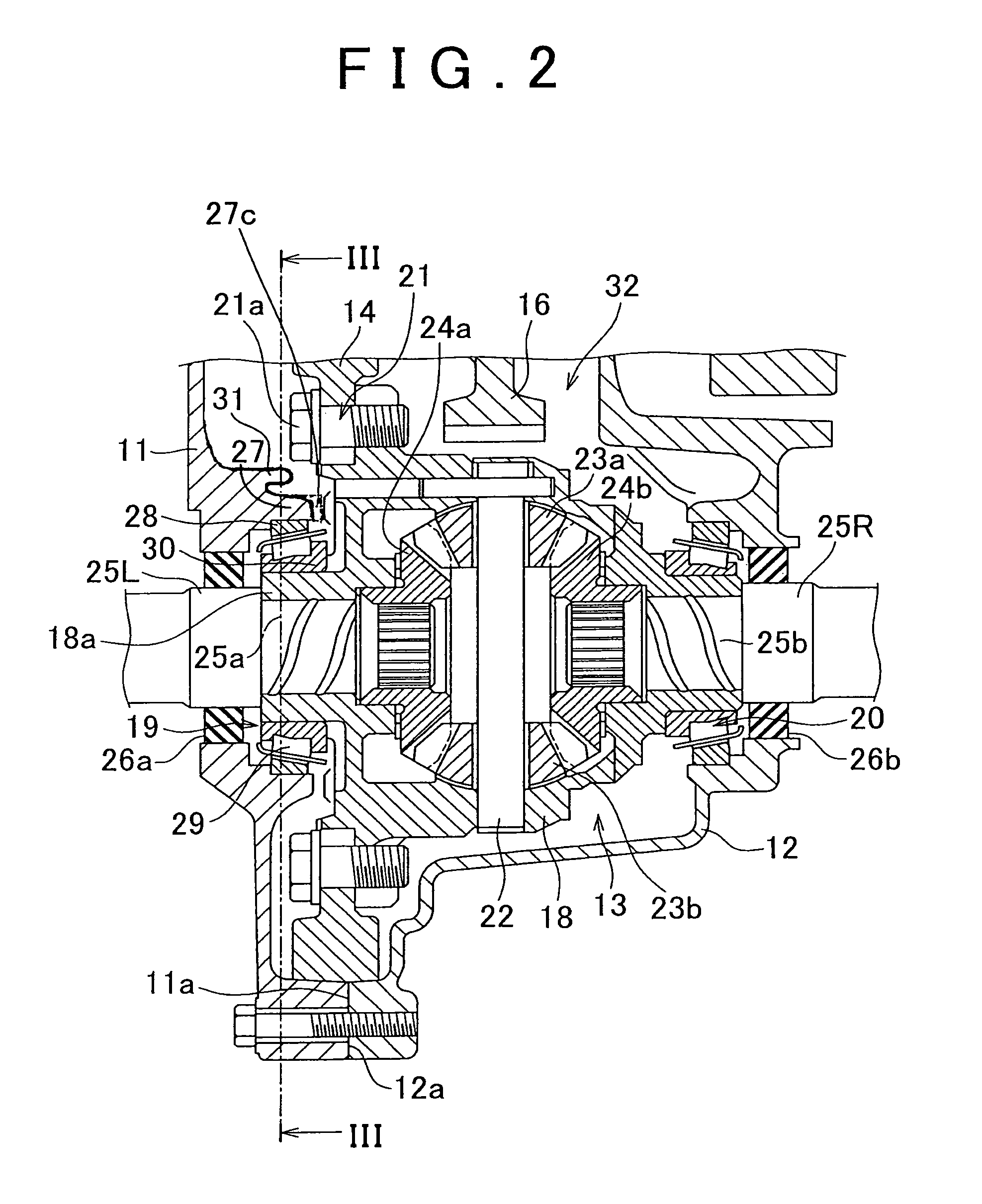
[0035]First the structure will be described. In FIG. 1, a power transmitting apparatus 10 includes a case 11, and this case 11 has an abutting surface 11a that contacts an abutting surface 12a of an opposing housing 12 (see FIG. 2).

[0036]In this power transmitting apparatus 10, a compound planetary gear set, not shown, that forms a speed change mechanism, a differential gear unit 13, to be described later, in which differential output to a drive shaft is possible, a d...


PUM


Abstract

In a lubrication structure of a differential gear unit, a case has a guide rib that extends over a certain area with respect to a rotation path of a head of a bolt when a ring gear rotates, and that protrudes out from the case toward the head of the bolt. Also, a through-hole that extends in a vertical direction is formed in an upper portion of a hollow supporting portion, and the guide rib has an oil reservoir that curves toward an upper end opening of the through-hole.

Description

INCORPORATION BY REFERENCE[0001]The disclosure of Japanese Patent Application No. 2010-097545 filed on Apr. 21, 2010 including the specification, drawings and abstract is incorporated herein by reference in its entirety.BACKGROUND OF THE INVENTION[0002]1 . Field of the Invention[0003]The invention relates to a lubrication structure of a differential gear unit. More particularly, the invention relates to a lubrication structure of a differential gear unit that lubricates a bearing that rotatably supports a differential case that houses a differential mechanism therein by a hollow supporting portion of a case of a power transmitting apparatus.[0004]2 . Description of the Related Art[0005]A differential gear unit incorporated in a transaxle of a vehicle such as an automobile includes a housing portion and a differential case that is rotatably housed in the housing portion. A drive pinion that is driven by a propeller shaft or the like is rotatably housed in the housing portion, and a r...

Claims


Application Information

Patent Timeline
Patent Type & Authority Patents(United States)
IPC IPC(8): F16H57/037F16H57/039F16H48/38F16H57/04B60K17/16F16H57/038F16B31/02F16H57/02
CPCF16H57/0457F16H57/0423F16H57/0483F16H57/0471Y10T74/2186
Inventor KIMURA, HIROMICHIKUWAHARA, TAKESHIKITAHATA, TAKESHIOBATA, TATSUOTANAE, MASAHIRO
Owner TOYOTA JIDOSHA KK
Why Eureka
Try Eureka