Heated annulus chuck

a technology of annulus chuck and heat sink, which is applied in the direction of semiconductor/solid-state device manufacturing, basic electric elements, electric apparatus, etc., can solve the problems of significant and time-consuming changes to the clamping device, and achieve the effect of minimizing downtime, high temperature processing, and adequate clamping force on the workpi

Active Publication Date: 2014-08-05
AXCELIS TECHNOLOGIES
View PDF33 Cites 0 Cited by
  • Summary
  • Abstract
  • Description
  • Claims
  • Application Information

AI Technical Summary

Benefits of technology

[0005]The inventors appreciate a need for an improved electrostatic clamp, wherein both high temperature processing and low temperature processing can be achieved via a single ESC capable of receiving and supporting various sized workpieces, while adequately maintaining a clamping force on the workpiece, and minimizing downtime caused by changing clamping devices.

Problems solved by technology

Further, depending on desired heating and / or cooling of the workpiece during processing for certain applications, significant and time-consuming changes to the clamping device may be necessitated in order to achieve the desired processing.

Method used


Image

  • Heated annulus chuck
  • Heated annulus chuck
  • Heated annulus chuck

Examples


Embodiment Construction

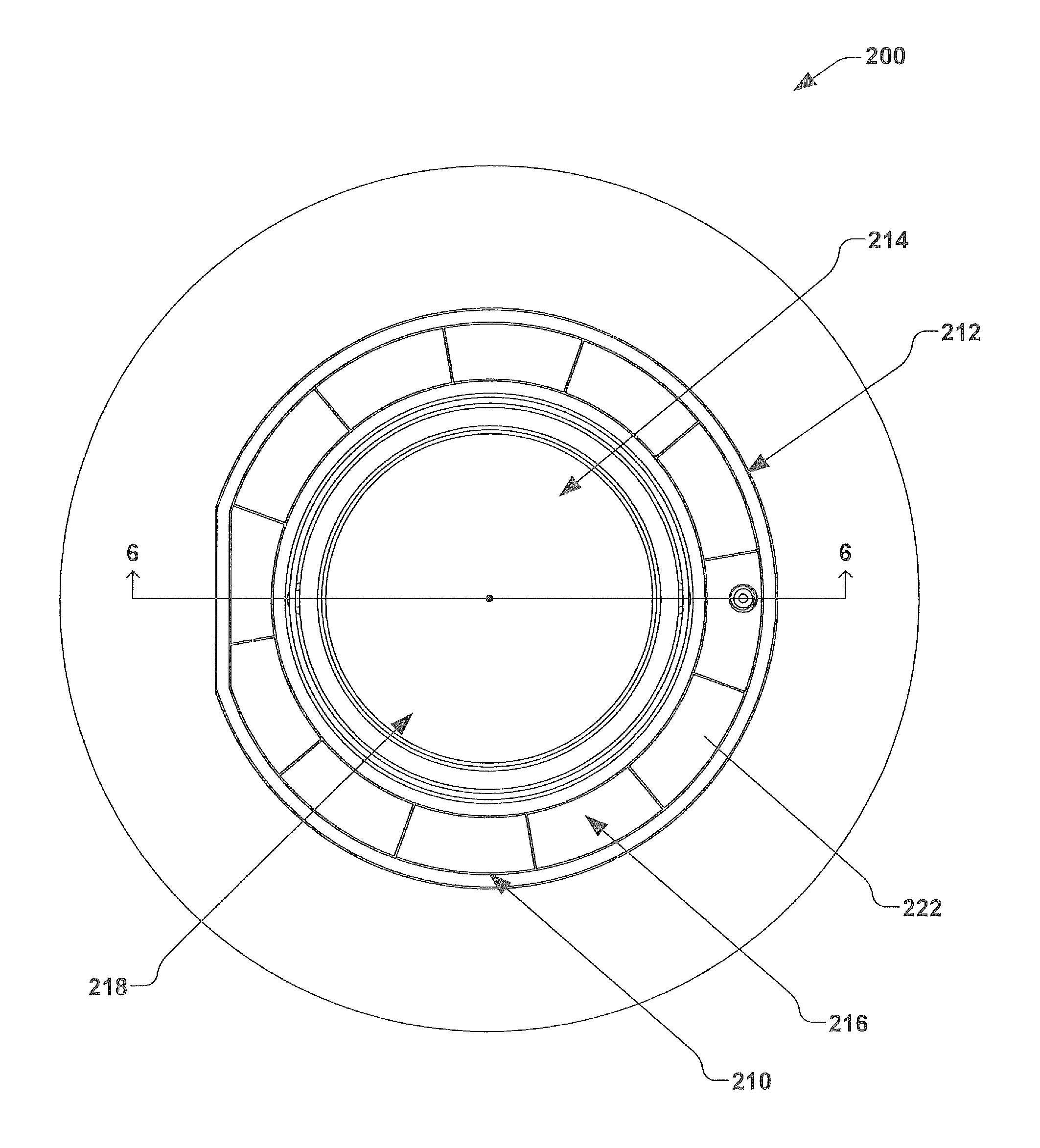
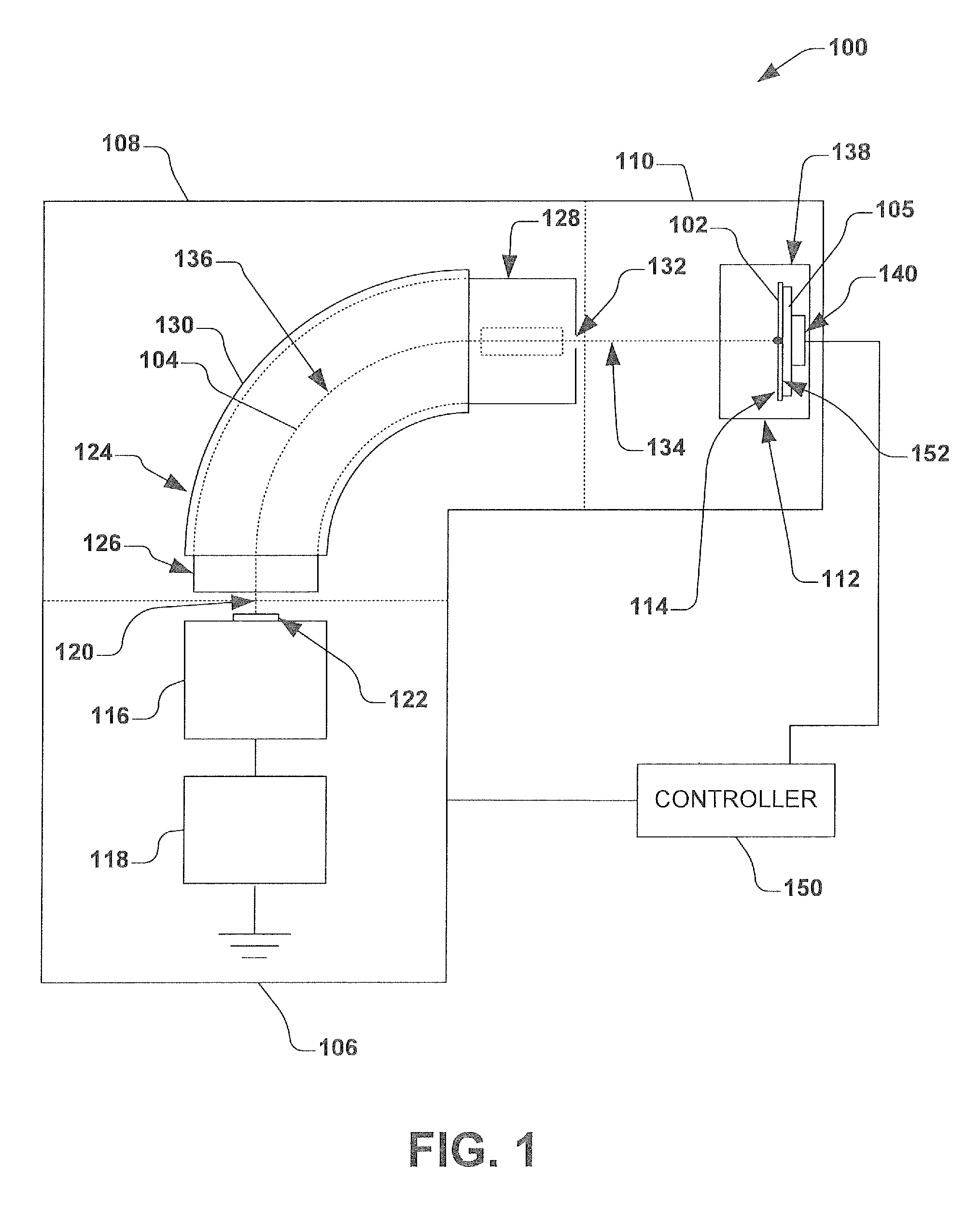
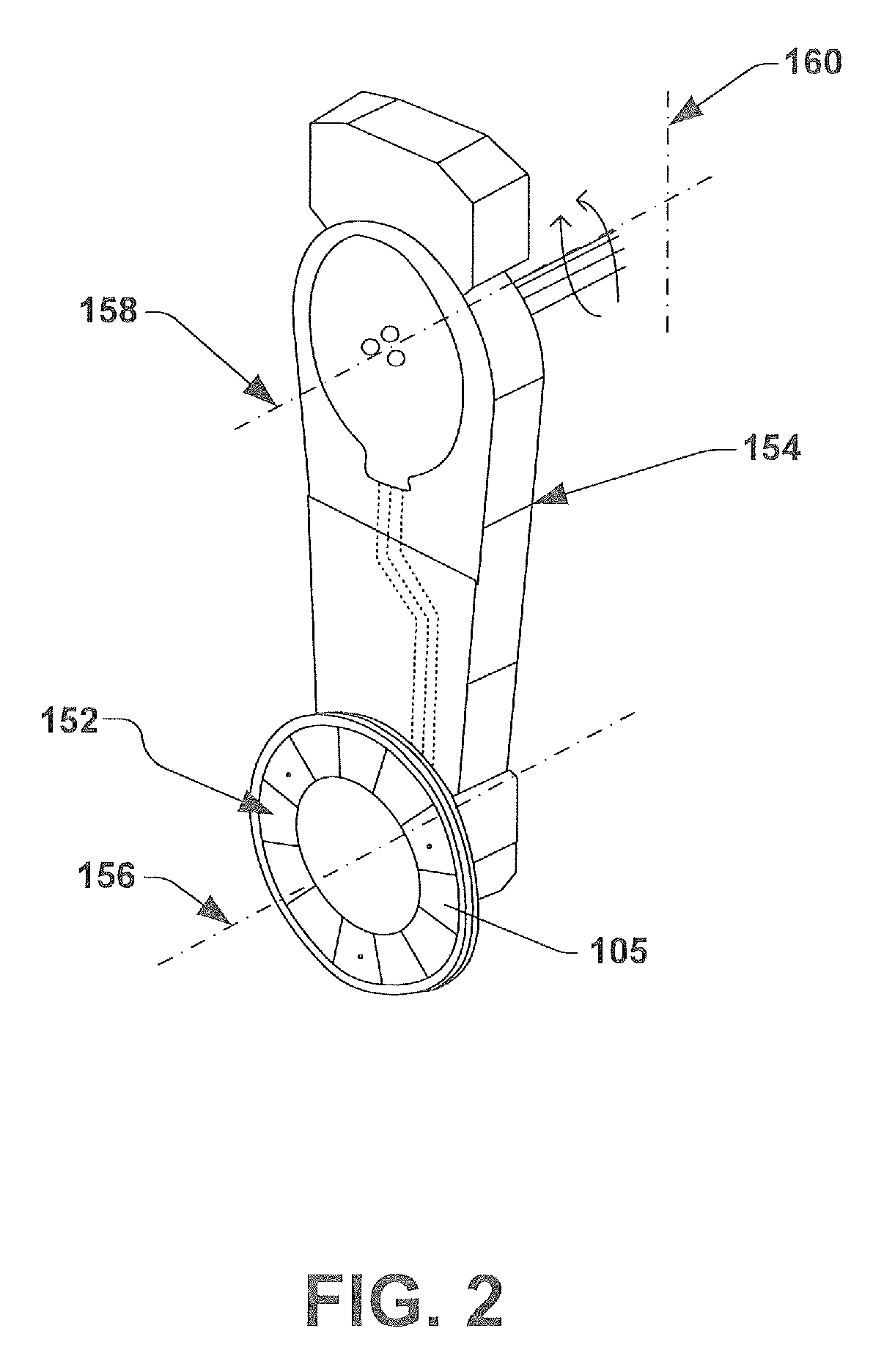
[0024]The present disclosure is directed generally toward an electrostatic clamp (ESC), also called an electrostatic chuck, that provides both clamping and temperature control of various-sized workpieces using the same electrostatic clamp. The disclosure is further directed to a clamping mechanism and method that enables heating workpieces of various sizes in a semiconductor processing system, wherein the workpieces can be maintained in a fixed position on a clamping surface by either electrostatic forces, mechanical forces, or both.

[0025]Accordingly, the present invention will now be described with reference to the drawings, wherein like reference numerals may be used to refer to like elements throughout. It should be understood that the description of these aspects are merely illustrative and that they should not be interpreted in a limiting sense. In the following description, for purposes of explanation, numerous specific details are set forth in order to provide a thorough unde...


PUM


Abstract

A clamping device and method is provided for securing first and second workpieces having different sizes to a clamping device and providing thermal conditioning thereto. An electrostatic clamping plate having a diameter associated with the first workpiece surrounds a central portion of the clamp. A non-electrostatic central portion provides a heater within the annulus, wherein the central portion has a diameter associated with the second workpiece. A workpiece carrier is provided, wherein the workpiece carrier is configured to hold the second workpiece above the heater, and wherein a diameter of the workpiece carrier is associated with the electrostatic clamping plate annulus. The annulus selectively electrostatically clamps the workpiece carrier or a circumferential portion of the first workpiece to its clamping surface, therein selectively maintaining a position of the first or second workpiece with respect to the annulus or non-electrostatic central portion.

Description

REFERENCE TO RELATED APPLICATION[0001]This application claims priority to and the benefit of U.S. Provisional Application Ser. No. 61 / 352,665 which was filed Jun. 8, 2010, entitled “HEATED ANNULUS CHUCK”, and U.S. Provisional Application Ser. No. 61 / 352,554 which was also filed Jun. 8, 2010, entitled “HEATED ELECTROSTATIC CHUCK INCLUDING MECHANICAL CLAMP CAPABILITY AT HIGH TEMPERATURE”, the entireties of which are hereby incorporated by reference as if fully set forth herein.FIELD OF THE INVENTION[0002]The present invention relates generally to semiconductor processing equipment, including but not limited to, ion implantation systems, and more specifically to an electrostatic chuck having an electrostatic annulus and a heated center portion for use in ion implantation applications.BACKGROUND OF THE INVENTION[0003]Electrostatic clamps or chucks (ESCs) are often utilized in the semiconductor industry for clamping and maintaining workpieces or substrates in a fixed position relative to...

Claims


Application Information

Patent Timeline
Patent Type & Authority Patents(United States)
IPC IPC(8): H01L21/687
CPCH01L21/6831H01L21/68728
Inventor LEE, WILLIAM DAVISCOOK, GARY M.JUSTESEN, PERRY J. I.PUROHIT, ASHWIN M.RATHMELL, ROBERT D.WEED, ALLAN D.
Owner AXCELIS TECHNOLOGIES
Why Eureka
Try Eureka