Shift control method in an automated manual transmission

a technology of automatic transmission and control method, which is applied in the direction of gearing control, gearing element, belt/chain/gearing, etc., can solve the problems of synchronized gear clutches, increasing the dimensions and weight of the gearshift transmission, and relatively expensive manufacturing, so as to achieve the effect of reducing the torque more quickly

Inactive Publication Date: 2014-03-11
ZF FRIEDRICHSHAFEN AG
View PDF10 Cites 2 Cited by
  • Summary
  • Abstract
  • Description
  • Claims
  • Application Information

AI Technical Summary

Benefits of technology

[0012]The clutch torque MK transmitted via the separator clutch from the drive motor to the input shaft of the gearshift transmission opposes the braking torque MBr applied by the transmission brake on the input shaft or on a countershaft in drive connection with the input shaft, and so brings about a rapid termination of the synchronization of the target gear or its gear clutch effected by the transmission brake. Since the clutch torque MK of the separator clutch is also supported by the driveshaft (crankshaft) of the drive motor, the braking of the driveshaft caused thereby also supports and accelerates the shift-related speed adaptation of the drive motor.
[0013]The speeding up of the target gear synchronization and thus of the upshift process as a whole, made possible by actuating the separator clutch, is achieved essentially in that with an unchanged braking torque MBr the transmission brake is actuated for a longer time and / or a higher braking torque MBr is set at the transmission brake.
[0020]In contrast, when there is a lower speed difference ΔnGK, during the torque decrease phase the clutch torque MK of the separator clutch is reduced more rapidly than when the speed difference ΔnGK is larger, in order to maintain a speed difference ΔnGK that is advantageous for the meshing of the gear clutch of the target gear and to avoid undesired acceleration of the input shaft of the gearshift transmission by the clutch torque MK of the separator clutch.
[0022]In this way, when the target gear synchronization by the transmission brake is more rapid the clutch torque MK of the separator clutch during the torque reduction phase is reduced more rapidly and to a greater extent than when synchronization is slower, in order to counteract the slowing down of the input shaft by the braking torque MBr of the transmission brake at the right time and effectively, and in the torque reduction phase when the target gear synchronization is more rapid, the torque is reduced more rapidly than when synchronization is slower, in order to maintain a speed difference ΔnGK that is advantageous for the meshing of the gear clutch of the target gear and to avoid undesired acceleration of the input shaft of the gearshift transmission by the clutch torque MK of the separator clutch.
[0023]Thus, by virtue of the method according to the invention, during an upshift the synchronization of the target gear or its gear clutch, and so also the upshift as a whole, are substantially accelerated without the need for special design measures for this. The method according to the invention can easily be adopted in an existing clutch- or transmission-control unit in the form of a program.

Problems solved by technology

Such lock-synchronized gear clutches, however, are of a relatively complex structure and are therefore relatively expensive to manufacture.
Moreover, within the gearshift transmission, synchronized gear clutches take up a relatively large amount of space thus increasing the dimensions and weight of the gearshift transmission.
Besides, since the way in which the synchronizer device works involves wear, the life of a gearshift transmission provided with synchronized gear clutches is necessarily limited.
However, in a manual transmission provided with unsynchronized gear clutches separate synchronization of the target gear concerned or the gear clutch associated with it is necessary.
However, the substantially constant braking torque MBr of the transmission brake may deviate from a nominal value due to external influences such as the ambient or operating temperature at the time and the wear condition of the friction linings, whereby the synchronization of the target gear in an upshift can be slowed down or speeded up.
However, these requirements cannot be fulfilled solely by a transmission brake whose braking torque MBr is constant over the speed difference ΔnGK at the gear clutch which is to be reduced.
Thus, at a high braking torque MBr the transmission brake can no longer be used below a certain speed difference ΔnGK, or the transmission brake may have such a low braking torque MBr that the synchronization of the target gear and hence the upshift process as a whole are greatly delayed.

Method used


Image

  • Shift control method in an automated manual transmission
  • Shift control method in an automated manual transmission

Examples


Embodiment Construction

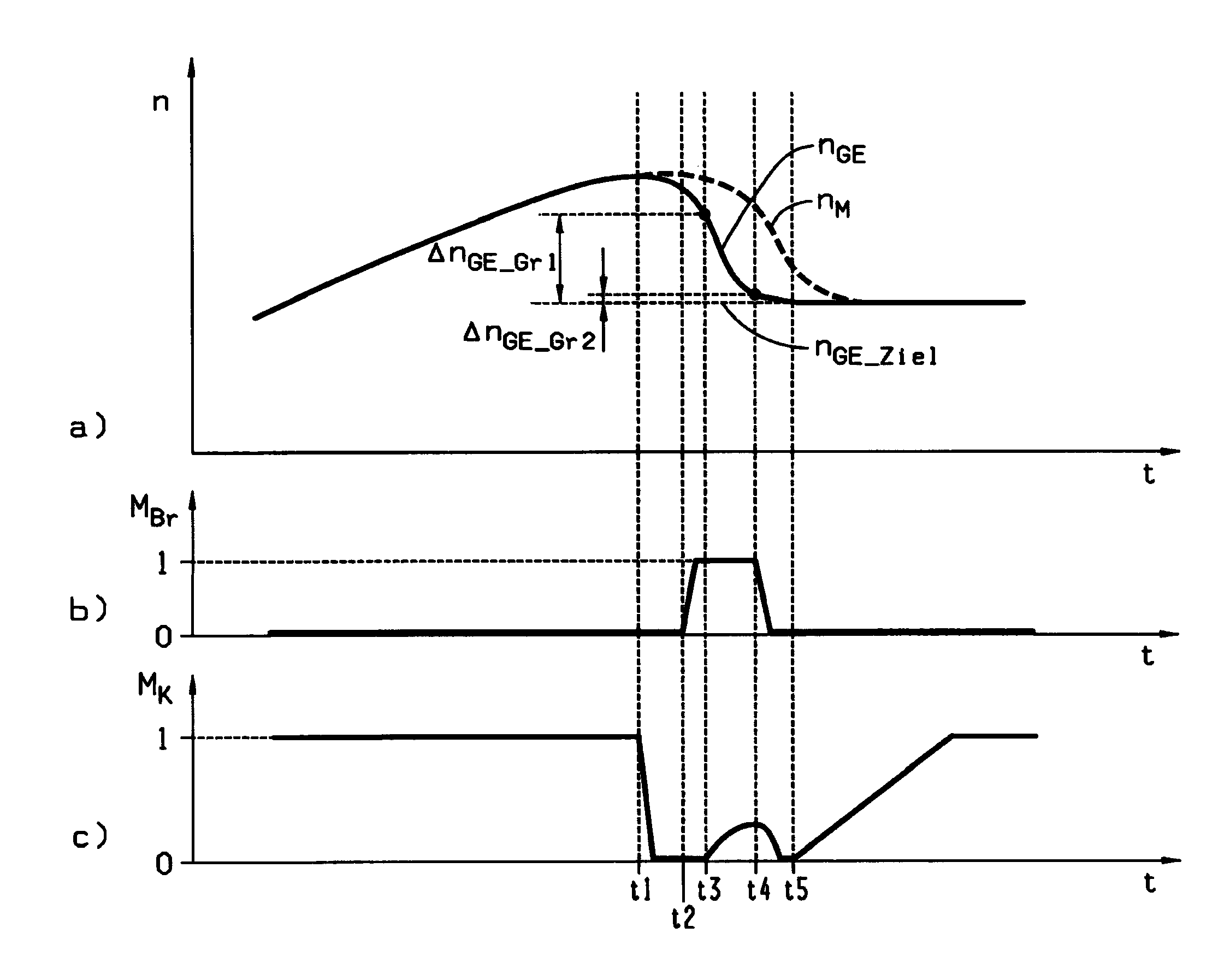
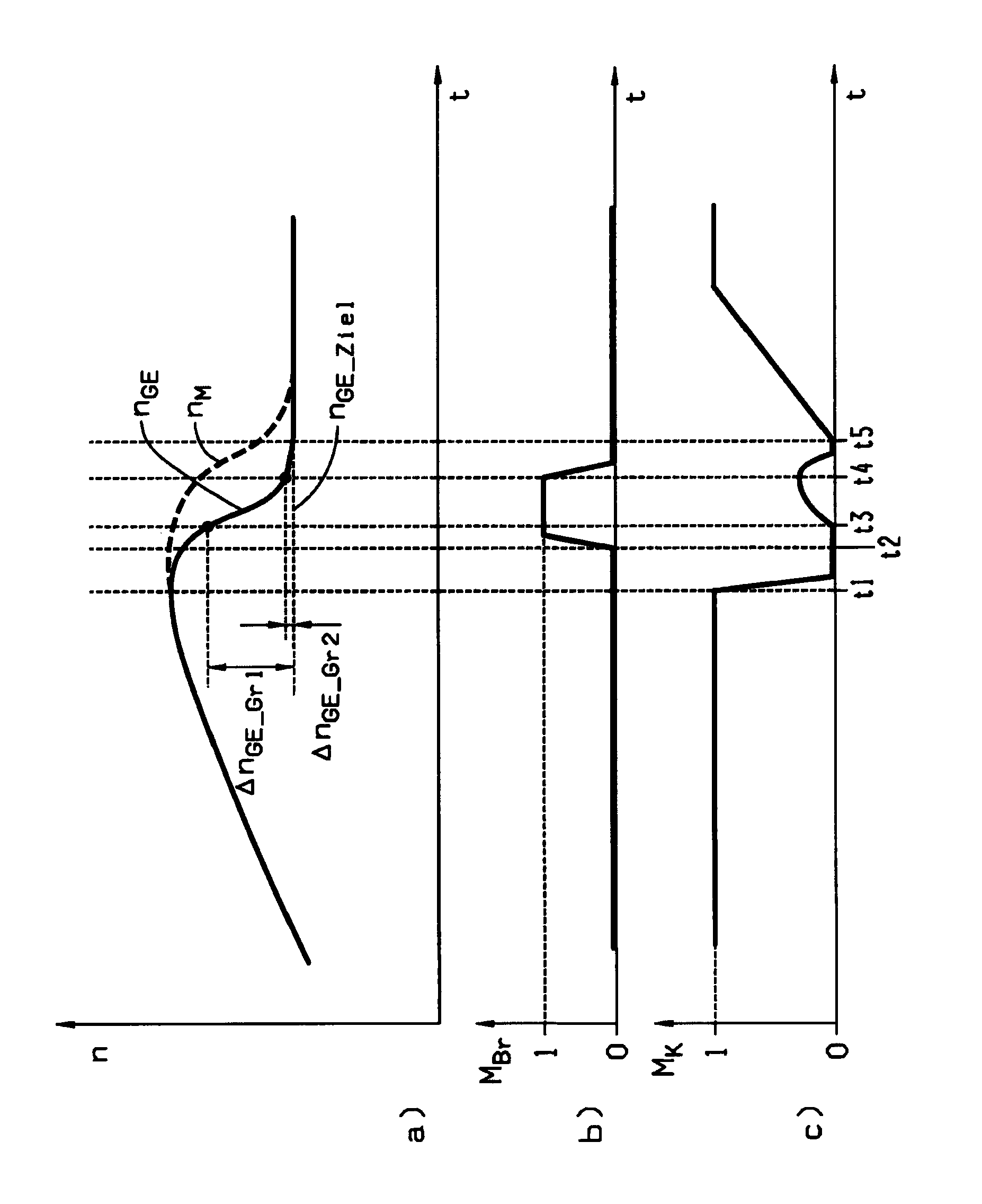
[0025]In the diagrams of FIG. 1, for an upshift sequence according to the invention the time variations of characteristic operating parameters of a drivetrain are reproduced, the drivetrain comprising an automated gearshift transmission provided with unsynchronized gear clutches, whose input shaft is connected via an automated, controllable separator clutch with the driveshaft of a drive motor, and which also comprises a transmission brake which is in drive connection with the input shaft. Part-diagram a) shows the speed variations of the input shaft nGE of the gearshift transmission and of the driveshaft of the drive motor nM, part-diagram b) shows the torque variation MBr of the transmission brake, and part-diagram c) shows the torque variation of the torque MK that can be transmitted by the separator clutch.

[0026]At the beginning of the upshift process, from time t1 the load reduction at the drive motor and the full disengagement of the separator clutch take place almost simultan...


PUM


Abstract

A shift control method for an automated gearshift transmission arranged in a drivetrain of a motor vehicle, between a drive motor and an axle drive, which is provided with unsynchronized gear clutches and whose input shaft can be connected to the driveshaft of the drive motor by an automatically controllable separator clutch such that, for an upshift, the synchronization of the target gear takes place with the separator clutch disengaged by setting a substantially constant braking torque at a transmission brake in driving connection with the input shaft. In order to speed up the shift sequence, without additional design measures, as the input speed of the gear clutch of the target gear approaches its output speed, to complete the synchronization, the separator clutch is partially engaged and then disengaged again substantially simultaneously as the transmission brake is released.

Description

[0001]This application is a National Stage completion of PCT / EP2009 / 053348 filed Mar. 23, 2009, which claims priority from German patent application serial no. 10 2008 001 686.1 filed May 9, 2008.FIELD OF THE INVENTION[0002]The invention concerns a shift control method for an automated manual transmission arranged in a drivetrain of a motor vehicle between a drive motor and an axle drive, which is provided with unsynchronized gear clutches and whose input shaft can be connected by means of an automated, controllable separator clutch to the driveshaft of the drive motor, such that during an upshift the synchronization of the target gear takes place with the separator clutch open, by setting a substantially constant braking torque at a transmission brake which is in drive connection with the input shaft.BACKGROUND OF THE INVENTION[0003]In a gearshift transmission, when shifting between a gear under load and a target gear, after the loaded gear has been disengaged a speed difference oc...

Claims


Application Information

Patent Timeline
Patent Type & Authority Patents(United States)
IPC IPC(8): B60W10/02
CPCF16H61/0403F16H2061/0411F16H2306/48
Inventor DOBELE, BERNDWIENCEK, NORBERT
Owner ZF FRIEDRICHSHAFEN AG
Why Eureka
Try Eureka