Thermal management system for vehicle

a technology for managing systems and vehicles, applied in vehicle sub-unit features, electric propulsion mountings, lighting and heating apparatuses, etc., can solve the problems of difficult to reduce the temperature and pressure of refrigerant, increase the power consumption, and high starting torque, so as to prevent the temperature from being high, increase the temperature, and reduce the pressure of the high-pressure side heat exchanger

Active Publication Date: 2018-09-04
DENSO CORP
View PDF17 Cites 3 Cited by
  • Summary
  • Abstract
  • Description
  • Claims
  • Application Information

AI Technical Summary

Benefits of technology

[0009]When the compressor is stopped in this operating state, if the pump stops at the same time as the compressor does, the cooling of the coolant liquid by the external heat exchanger is quickly terminated, possibly keeping the refrigerant-coolant heat exchanger at a high temperature. When the secondary cooling circuit receives heat from an engine or the like, the temperatures of the refrigerant-coolant heat exchanger and the coolant liquid might increase.
[0010]If the refrigerant-coolant heat exchanger is kept at high temperature, the pressure on the refrigerant side of the refrigerant-coolant heat exchanger also remains high, causing the compressor to discharge the refrigerant toward the higher pressure portion at the start-up of the compressor, which needs a high starting torque, resulting in increased power consumption.
[0012]The present disclosure has been made in view of the foregoing matter, and it is an object of the present disclosure to provide a thermal management system for a vehicle that suppresses degradation in cycle efficiency when restarting a compressor.
[0014]Since the operation of the first pump is continued even after the compressor is stopped, the heat medium can be cooled by the heat medium-outside air heat exchanger. Thus, the heat medium can be prevented from keeping its temperature high or from increasing its temperature after the compressor is stopped, thereby decreasing the pressure of the high-pressure side heat exchanger. As a result, the temperature and pressure of the refrigerant can be prevented from increasing when restarting the compressor, and thereby it can suppress the degradation in cycle efficiency.

Problems solved by technology

If the refrigerant-coolant heat exchanger is kept at high temperature, the pressure on the refrigerant side of the refrigerant-coolant heat exchanger also remains high, causing the compressor to discharge the refrigerant toward the higher pressure portion at the start-up of the compressor, which needs a high starting torque, resulting in increased power consumption.
When the compressor is restarted with the temperature of the coolant liquid increased, the refrigerant-coolant heat exchanger allows the refrigerant to exchange heat with the high-temperature coolant liquid, making it difficult to decrease the temperature and pressure of the refrigerant.
Also, in this case, power consumption of the compressor might increase, disadvantageously degrading cycle efficiency.

Method used


Image

  • Thermal management system for vehicle
  • Thermal management system for vehicle
  • Thermal management system for vehicle

Examples


first embodiment

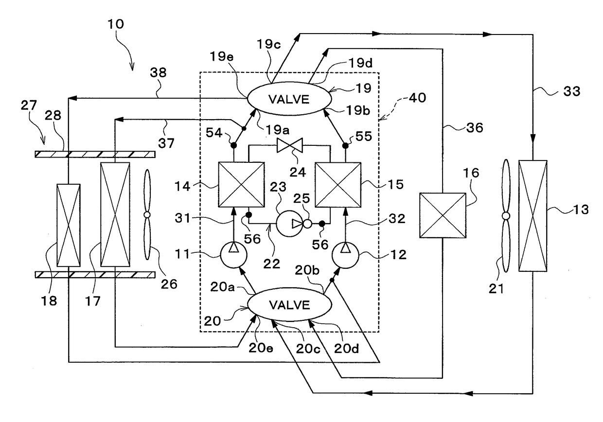
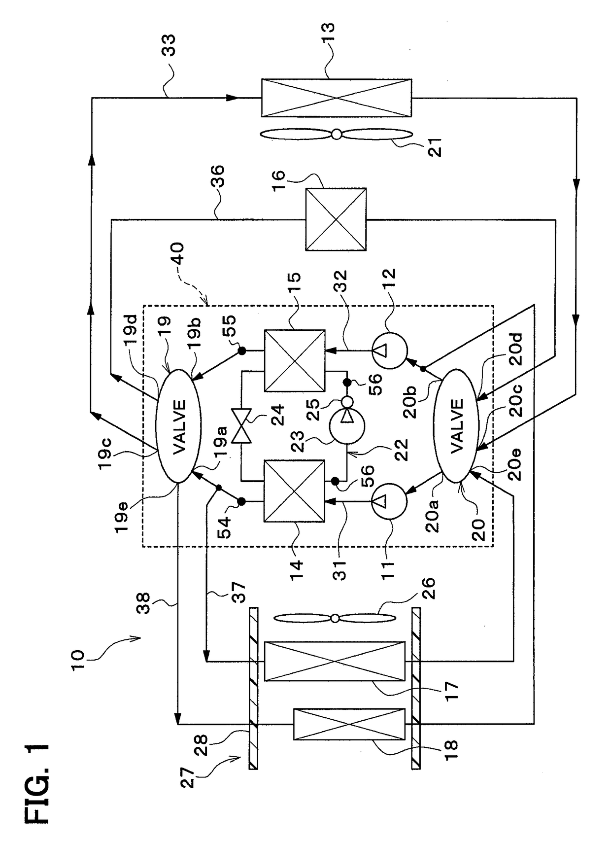
[0023]A vehicle thermal management system 10 shown in FIG. 1 is used to adjust various devices mounted on a vehicle or an interior of the vehicle to appropriate temperatures. In this embodiment, the vehicle thermal management system 10 is applied to a hybrid vehicle that can obtain the driving force for traveling from both an engine (internal combustion engine) and a traveling electric motor.

[0024]The hybrid vehicle of this embodiment is configured as a plug-in hybrid vehicle that can charge the battery (vehicle-mounted battery) mounted on the vehicle, with power supplied from an external power source (commercial power source) during stopping of the vehicle. For example, a lithium ion battery can be used as the battery.

[0025]The driving force output from the engine is used not only to cause the vehicle to travel, but also to operate a power generator. The power generated by the power generator and the power supplied from an external power source can be stored in the battery. Such po...

second embodiment

[0150]In this embodiment, as shown in FIG. 7, an evaporator 60 is provided in place of the coolant cooler 14 and the cooler core 17 of the above-mentioned first embodiment.

[0151]The evaporator 60 is an air cooling heat exchanger (air-refrigerant heat exchanger) that cools the ventilation air into the vehicle interior by exchanging heat between the low-pressure side refrigerant in the refrigeration cycle 22 and the ventilation air into the vehicle interior.

[0152]The evaporator 60 evaporates a low-pressure refrigerant by exchanging heat between the low-pressure refrigerant decompressed and expanded by the expansion valve 24 and the ventilation air into the vehicle interior. The gas-phase refrigerant evaporated at the evaporator 60 is drawn into and compressed by the compressor 23.

[0153]Also in this embodiment, an air-cooling operation (radiator heat dissipation mode) can be performed in the same manner as in the first embodiment.

[0154]In the radiator heat dissipation mode, the control...


PUM


Abstract

A thermal management system for a vehicle includes a high-temperature side pump that draws and discharges a heat medium, a compressor that draws and discharges a refrigerant in a refrigeration cycle, a high-pressure side heat exchanger that exchanges heat between a high-pressure side refrigerant in the refrigeration cycle and the heat medium circulated by the high-temperature side pump, a heat medium-outside air heat exchanger that exchanges heat between the heat medium circulated by the high-temperature side pump and outside air, and a pump control unit that controls an operation of the high-temperature side pump such that the operation of the high-temperature side pump is continued even after the compressor is stopped. Thus, the cycle efficiency exhibited when restarting the compressor can be improved.

Description

CROSS REFERENCE TO RELATED APPLICATIONS[0001]This application is a U.S. National Phase Application under 35 U.S.C. 371 of International Application No. PCT / JP2015 / 000860 filed on Feb. 23, 2015 and published in Japanese as WO 2015 / 133083 A1 on Sep. 11, 2015. This application is based on and claims the benefit of priority from Japanese Patent Application No. 2014-042925 filed on Mar. 5, 2014. The entire disclosures of all of the above applications are incorporated herein by reference.FIELD OF THE INVENTION[0002]The present disclosure relates to a thermal management system for use in vehicles.BACKGROUND ART[0003]Conventionally, for example, Patent Document 1 describes an automobile temperature-adjustment device including a heat pump and a secondary cooling circuit. In the related art, the heat pump includes a compression type main refrigerant circuit that takes heat from a low-temperature heat source, and transfers at least part of that heat to a high-temperature heat source. The secon...

Claims


Application Information

Patent Timeline
Patent Type & Authority Patents(United States)
IPC IPC(8): B60H1/00F25B1/00B60K11/02B60K6/22B60K1/00
CPCB60H1/00899B60H1/00807B60H1/00828B60H1/00885B60K6/22B60K11/02F25B1/00B60H1/00385Y10S903/904B60H2001/00928B60K2001/003B60K2001/005B60K2001/006B60Y2200/92B60Y2400/88B60Y2400/89B60H1/32284
Inventor MAKIHARA, MASAMICHIYAMANAKA, TAKASHIOMI, YASUMITSUMIURA, KOJIENOMOTO, NORIHIKOKAKEHASHI, NOBUHARU
Owner DENSO CORP
Why Eureka
Try Eureka