Acceleration switch

a technology of acceleration switch and acceleration switch, which is applied in the direction of speed/acceleration/shock measurement, measurement devices, instruments, etc., can solve the problems of affecting the braking effect of the braking portion, and causing a relatively large disturbance to the acceleration switch. , to achieve the effect of preventing an erroneous determination, reducing the energy of movement of the inertia ball, and increasing the braking portion

Active Publication Date: 2011-04-05
UBUKATA IND CO LTD
View PDF13 Cites 5 Cited by
  • Summary
  • Abstract
  • Description
  • Claims
  • Application Information

AI Technical Summary

Benefits of technology

An object of the present invention is to provide an acceleration switch which can prevent erroneous determination by the determining device due to disturbance such as shock.
According to the acceleration switch of the invention, the rolling of the inertia ball is suppressed by the braking member of the braking portion. A braking effect of the braking portion is relatively increased particularly at a stage where energy of movement of the inertia ball is reduced as on the occasion immediately before termination of the rolling of the inertia ball. As a result, quick termination of the rolling of the inertia ball can be realized, thereby preventing an erroneous determination due to continuance of electrical conduction of the housing and the contact member.

Problems solved by technology

On the other hand, disturbance due to shock is sometimes given to an apparatus installed with the acceleration switch when a person or substance strikes the apparatus.
Furthermore, when a duration of conductive signal exceeds a predetermined time period, the determining device can also determine that the acceleration switch is in an abnormal condition in which an apparatus installed with the acceleration switch has fallen over or inclined.
However, when a person or a substance happens to strike against an apparatus (a gas meter, for example) installed with the acceleration switch, a relatively larger disturbance is directly given to the acceleration switch.
Accordingly, although there is actually no problem, the determining device erroneously determines that the apparatus installed with the acceleration switch is in a fallen state.
However, even the foregoing conventional acceleration switches deliver a conduction signal corresponding with the conduction signal due to an earthquake or the like in rare cases under specified conditions, so that the determining devices make an erroneous determination.
However, when the number of movable contacts elastically contacting the inertia ball is reduced, a force suppressing the movement of the inertia ball (braking force) is reduced such that it becomes difficult to terminate the rolling of the inertia ball.
Accordingly, the gas meters are subjected to disturbance such as shock in many cases.

Method used


Image

  • Acceleration switch
  • Acceleration switch
  • Acceleration switch

Examples


first embodiment

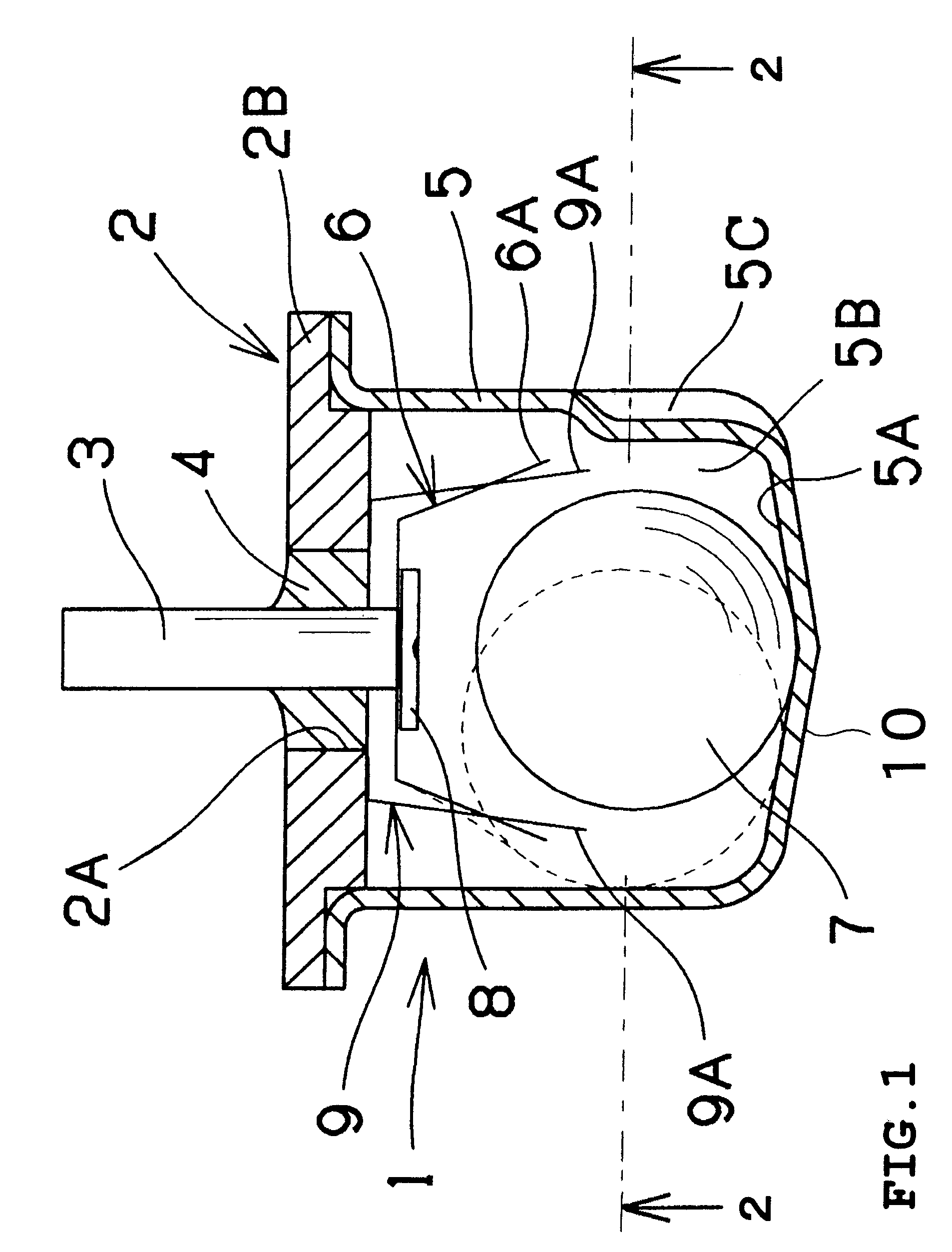
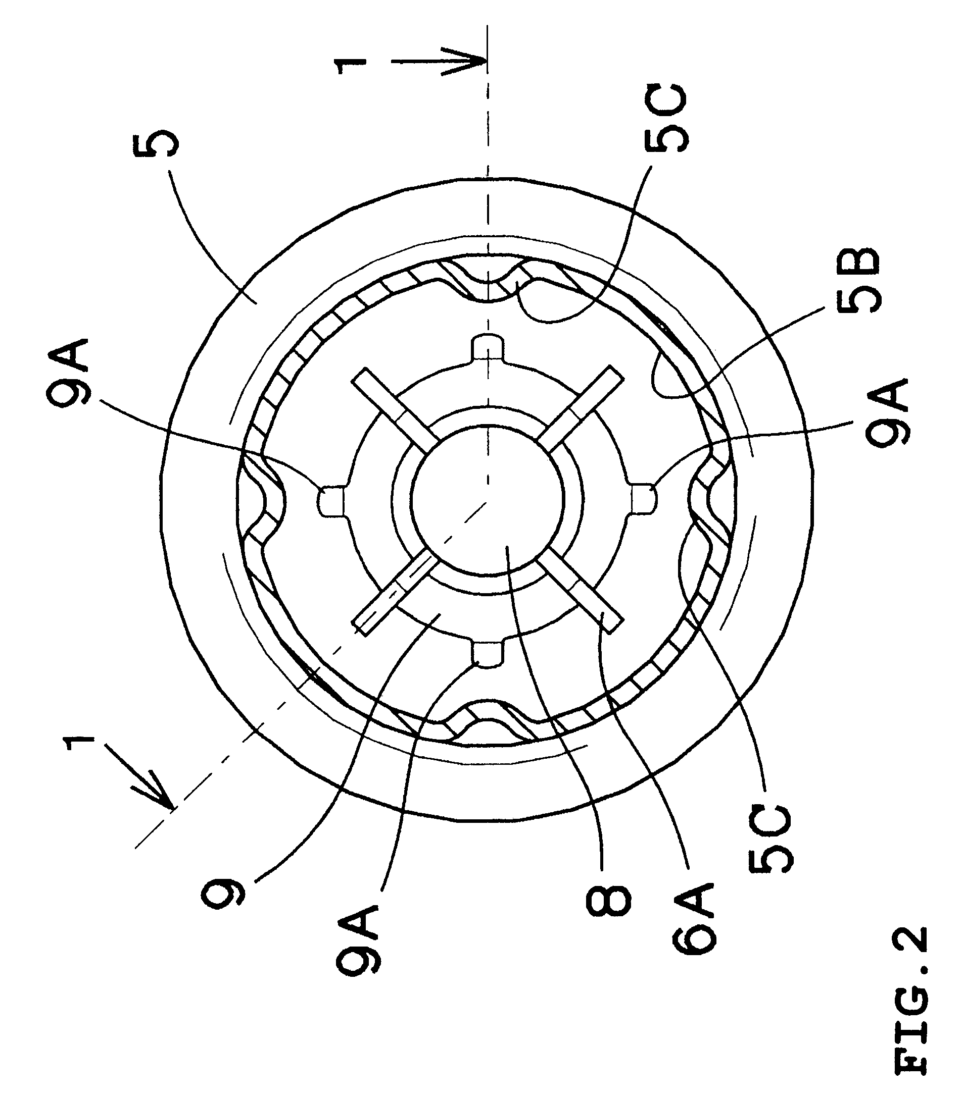
A first embodiment of the invention will be described with reference to FIGS. 1 and 2. FIG. 1 is a longitudinal side section taken along line 1-1 in FIG. 2. FIG. 2 is a cross-sectional bottom view taken along line 2-2 in FIG. 1.

The acceleration switch 1 includes a header plate 2 made of a metal and formed into a circular shape. The header plate 2 has a through hole 2A formed through a central part thereof. An electrically conductive lead terminal 3 is inserted through the through hole 2A. The lead terminal 3 is fixed by an electrically insulating filler 4 such as glass. The header plate 2 has a flange 2B formed on a circumferential edge thereof.

A housing 5 is made of a metal and formed into the shape of a bottomed cylinder. The housing 5 has an opening end hermetically fixed to the flange 2B by a process such as a ring projection welding, whereby the header plate 2 and the housing 5 constitute a hermetic container 10. As a result, a volume of contamination preventive gas such as nit...

second embodiment

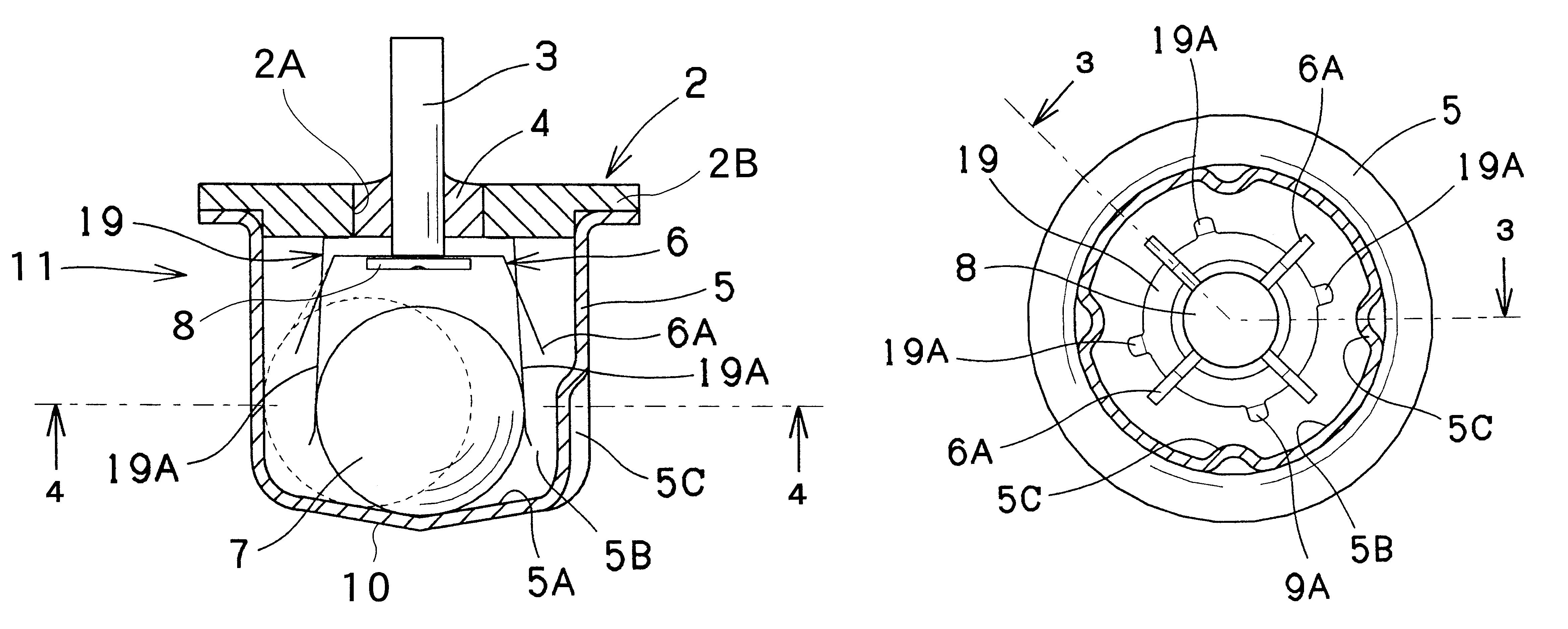
A second embodiment of the present invention will now be described with reference to FIGS. 3 and 4. FIG. 3 is a longitudinal side section of the acceleration switch taken along line 3-3 in FIG. 4. FIG. 4 is a cross-sectional bottom view of the acceleration switch taken along line 4-4 in FIG. 3. Identical or similar parts in FIGS. 3 and 4 are labeled by the same reference symbols as in FIGS. 1 and 2, and the description of these parts will be eliminated.

In the acceleration switch 11, the braking portions 19A of the braking member 19 are extended so that portions of the braking portions 19A near to the distal ends normally come into contact with the inertia ball 7. In the first embodiment, the braking member 9 stops affecting the inertia ball 7 when the inertia ball 7 has moved inside the braking member 9. In the second embodiment, the braking effect can be obtained from each braking portion 19A when the inertia ball 7 is stationary. Consequently, the inertia ball 7 can be braked more...

third embodiment

A third embodiment of the present invention will now be described with reference to FIGS. 5 and 6. FIG. 5 is a longitudinal side section of the acceleration switch taken along line 5-5 in FIG. 6. FIG. 6 is a cross-sectional bottom view of the acceleration switch taken along line 6-6 in FIG. 5. Identical or similar parts in FIGS. 5 and 6 are labeled by the same reference symbols as in FIGS. 1 and 2, and the description of these parts will be eliminated.

In the acceleration switch 21, the number of the feather portions 26A (serving as movable contacts) is increased from four in the first embodiment to eight. With this, the number of the braking portions 29A of the braking member 29 is also increased to eight. Furthermore, the acceleration switch is structured so that during the rolling of the inertia ball 7 on the bottom 5A, the contact location of the inertia ball 7 and the braking member 29 (each braking portion 29A) is nearer to the central side of the housing 5 than the contact loc...


PUM


Abstract

An acceleration switch includes a closed container further including a cylindrical housing and a substantially circular metal header plate, a conductive lead terminal inserted through a hole of the header plate and hermetically fixed in the hole, a contact member secured to a distal end of the lead terminal and having a plurality of elastically deformable movable contacts substantially concentric about the distal end of the lead terminal, a conductive inertia ball accommodated in the container and caused to roll in the housing thereby to contact the movable contact, whereby the housing and the contact member are rendered conductive, and a braking member disposed between the movable contacts so as to be capable of urging the inertia ball in a direction of a center of the closed container. The braking member includes an elastically deformable braking portion which is extended so as to normally contact the inertia ball.

Description

CROSS-REFERENCE TO RELATED APPLICATIONSThis application is a National Phase Application based upon and claiming the benefit of priority to PCT / JP2006 / 314404, filed on Jul. 20, 2006, which is based upon and claims the benefit of priority to Japanese Patent Application No. 2005-213443, filed Jul. 22, 2005, the contents of both of which are incorporated herein by reference.FIELD OF THE INVENTIONThe present invention relates to an acceleration switch for use in seismoscopes or the like.BACKGROUND ARTAn acceleration switch in which an inertia ball (a metal ball or the like) is housed in a metal container is disclosed, for example, by Japanese Patent No. 2892559 (prior art document 1) or Japanese Patent No. 2887556 (prior art document 2).In these acceleration switches, an inertia ball is rollably housed in a metal housing serving as one electrode. The inertia ball normally remains stationary on a central bottom of the housing. A plurality of movable contacts comprised of contact members a...

Claims


Application Information

Patent Timeline
Patent Type & Authority Patents(United States)
IPC IPC(8): H01H35/02
CPCG01P15/135H01H35/142H01H35/14
Inventor WATANABE, MASAYUKITAKEDA, TERUYUKI
Owner UBUKATA IND CO LTD
Why Eureka
Try Eureka