Method and system for optically coupling a laser with a transducer in an energy assisted magnetic recording disk drive

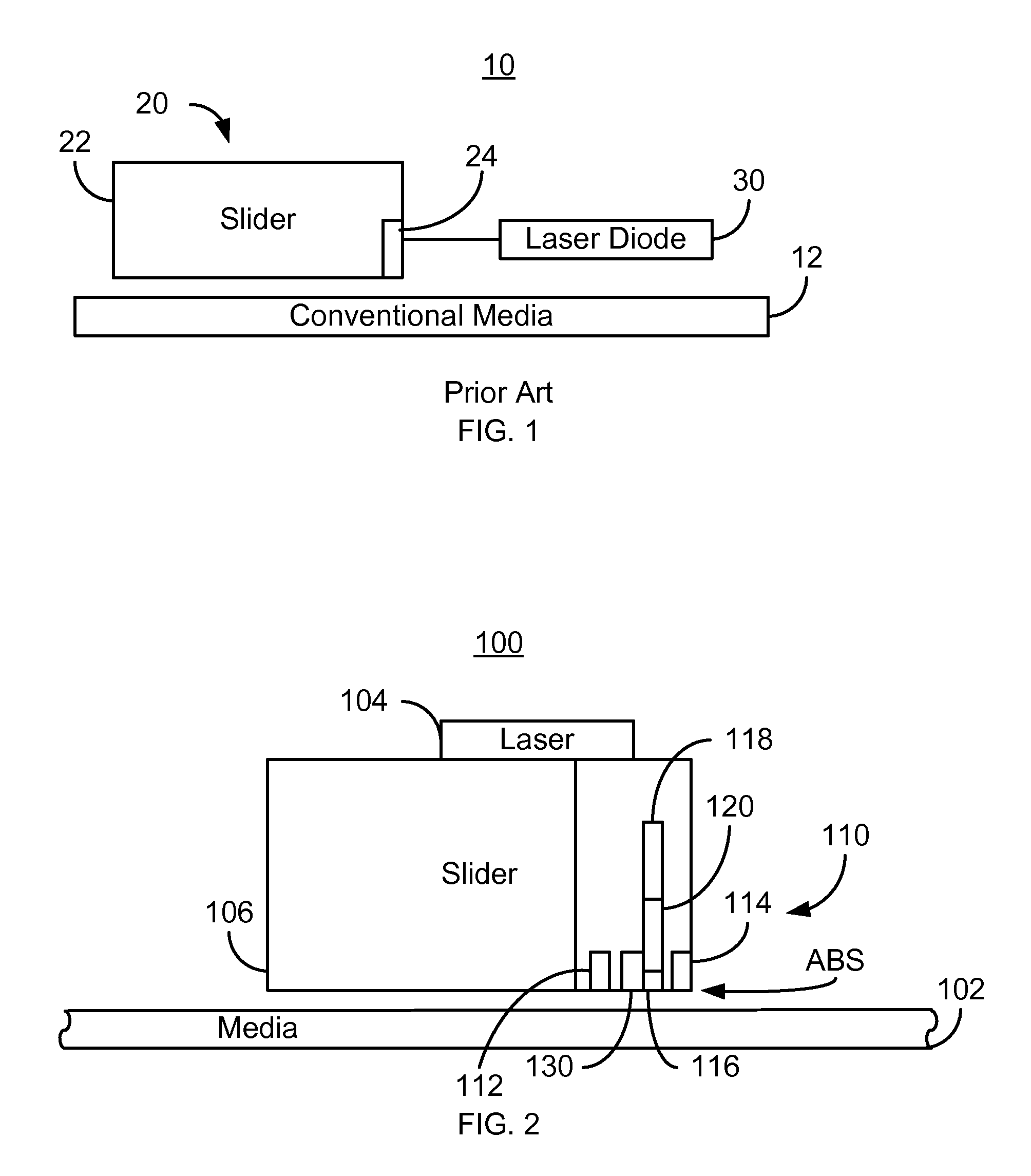
a technology of magnetic recording and laser, which is applied in the field of conventional energy assisted magnetic recording (eamr) disk drives, can solve the problems of difficult integration of laser b>30/b> with the slider b>22/b> in a manner that allows efficient light delivery, and the head performance may be adversely affected

Active Publication Date: 2014-03-11
WESTERN DIGITAL TECH INC
View PDF29 Cites 164 Cited by
  • Summary
  • Abstract
  • Description
  • Claims
  • Application Information

AI Technical Summary

Problems solved by technology

Although the conventional EAMR disk drive 10 may function, manufacturing the conventional EAMR disk drive 10 at an acceptable cost and with sufficient optical efficiency may be problematic.
More specifically, integration of the laser 30 with the slider 22 in a manner that allows for efficient light delivery may be challenging.
The optical efficiency of the EA

Method used


Image

  • Method and system for optically coupling a laser with a transducer in an energy assisted magnetic recording disk drive
  • Method and system for optically coupling a laser with a transducer in an energy assisted magnetic recording disk drive
  • Method and system for optically coupling a laser with a transducer in an energy assisted magnetic recording disk drive

Examples


Embodiment Construction

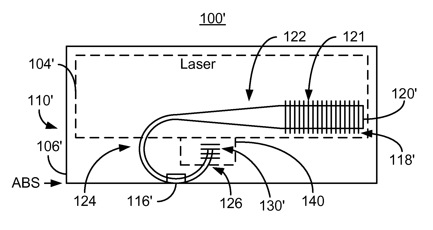
[0013]FIG. 2 is a diagram depicting a portion of an EAMR disk drive 100. For clarity, FIG. 2 is not to scale. For simplicity not all portions of the EAMR disk drive 100 are shown. In addition, although the disk drive 100 is depicted in the context of particular components other and / or different components may be used. In addition, although single components, such as lasers, are shown, multiple components may be used in other embodiments. Further, the arrangement of components may vary in different embodiments.

[0014]The EAMR disk drive 100 includes media 102, laser 104, a slider 106, and an EAMR transducer 110 that is optically coupled with the laser 104. In some embodiments, the laser 104 is a laser diode. Although shown as coupled with the back edge of the slider 106, the laser may be located elsewhere. For example, the laser 104 may be coupled to the trailing face of the slider 106, in proximity to the EAMR transducer 110.

[0015]The EAMR transducer 110 is coupled with the slider 10...


PUM


Abstract

A method and system for providing an energy assisted magnetic recording (EAMR) transducer coupled with a laser. The EAMR transducer has an air-bearing surface (ABS) configured to reside in proximity to a media during use. The EAMR transducer includes a write pole, at least one coil, a waveguide and an output device. The write pole is configured to write to a region of the media. The at least one coil is for energizing the write pole. The waveguide has an input optically coupled to the laser and configured to direct energy from the laser toward the ABS for heating the region of the media. The output device is optically coupled to the waveguide. The output device coupling out a portion of the energy not coupled to the media.

Description

BACKGROUND[0001]FIG. 1 depicts a side view of portion of a conventional energy assisted magnetic recording (EAMR) disk drive 10. The conventional EAMR disk drive 10 includes a recording media 12, a conventional EAMR head 20, and a conventional laser diode 30 that are typically attached to a suspension (not shown). The EAMR head 20 includes a slider 22 and EAMR transducer 24. Other components that may be part of the conventional EAMR disk drive 10 are not shown. The conventional slider 22 is typically attached to a suspension (not shown). A conventional EAMR transducer 24 is coupled with the slider 22 on the trailing face of the slider 22.[0002]The conventional EAMR transducer 24 includes a grating (not separately shown) that receives light from the laser diode. The light from the laser diode 30 is coupled into the grating and then provided to a waveguide (not shown) of the conventional transducer 24. The waveguide directs the light toward the conventional media 12. The light is typi...

Claims


Application Information

Patent Timeline
IPC IPC(8): G11B11/00
CPCG11B5/105G11B5/314G11B5/6088G11B2005/0021G11B11/00
Inventor HU, YUFENGLI, RUOLINTRAN, UT
Owner WESTERN DIGITAL TECH INC
Why Eureka
Try Eureka