Systems and methods for providing backup energy to a load

Inactive Publication Date: 2014-03-18
P10 IND INC
View PDF12 Cites 54 Cited by
  • Summary
  • Abstract
  • Description
  • Claims
  • Application Information

AI Technical Summary

Problems solved by technology

When utility power fails, the bridging energy system begins providing power to the critical load.
When utility power fails, the bridging energy system begins supplying power to the load.

Method used


Image

  • Systems and methods for providing backup energy to a load
  • Systems and methods for providing backup energy to a load
  • Systems and methods for providing backup energy to a load

Examples


Embodiment Construction

[0044]Preferred embodiments of the present disclosure are illustrated in the FIGs., like numerals being used to refer to like and corresponding parts of the various drawings.

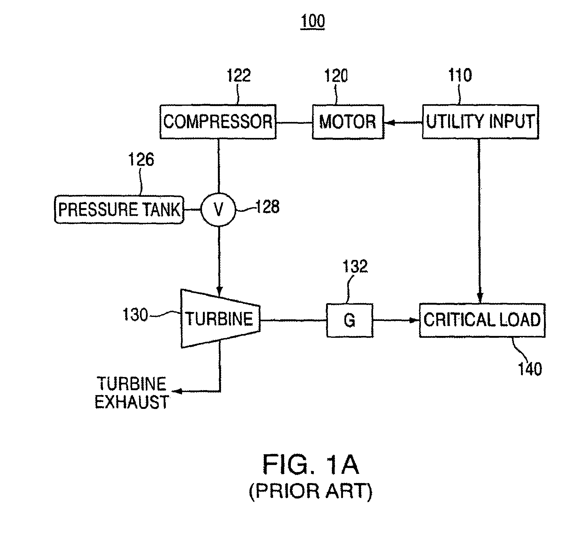
[0045]FIG. 1A shows a conventional CAS system for providing backup power to a load. CAS system 100 includes a primary power source, utility input 110, that provides input power to motor 120, which may be any conventional type of motor (e.g., a rotary electric machine). Motor 120 is coupled to compressor 122 such that when motor 120 is receiving input power from utility input 110, it drives compressor 122. Compressor 122, when driven by motor 120, supplies compressed air to pressure tank 126 through valve 128. Compressor 122 may be any type of compressor which compacts or compresses air (e.g., atmospheric air) to occupy a smaller space inside of pressure tank 126.

[0046]As shown in FIG. 1A, pressure tank 126 is coupled to compressor 122 through valve 128. It should be understood, however, that pressure tank 126 in...


PUM

PropertyMeasurementUnit
timeaaaaaaaaaa
timeaaaaaaaaaa
pressureaaaaaaaaaa

Abstract

Backup energy systems utilizing compressed air storage (CAS) systems and bridging energy systems to supply backup power to a load are provided. During a power failure, the bridging energy system provides backup power to the load at least until the CAS system begins supplying adequate power. In various embodiments, backup power capability is enhanced through the use of one or more exhaustless heaters, which are used to heat compressed air. The compressed air, in turn, drives a turbine which is used to power an electrical generator. In various embodiments, ambient air heat exchangers or other types of heat exchangers are used to heat compressed air prior to the compressed air being routed to the turbine, thereby increasing system efficiency. Backup power and backup HVAC are also provided by utilizing turbine exhaust, heat exchangers and various resistive heating elements.

Description

REFERENCES TO RELATED APPLICATIONS[0001]The present U.S. Utility Patent Application claims priority pursuant to 35 U.S.C. §120, as a continuation, to the following U.S. Utility Patent Application which is hereby incorporated herein by reference in its entirety and made part of the present U.S. Utility Patent Application for all purposes:[0002]1. U.S. Utility application Ser. No. 12 / 564,644, entitled “SYSTEM AND METHODS FOR PROVIDING BACKUP ENERGY TO A LOAD,” filed Sep. 22, 2009 now abandoned, which claims priority pursuant to 35 U.S.C. §120, as a divisional, to the following U.S. Utility Patent Applications which are hereby incorporated herein by reference in its entirety and made part of the present U.S. Utility Patent Application for all purposes:[0003]a. U.S. Utility application Ser. No. 10 / 361,728, entitled “SYSTEM AND METHODS FOR PROVIDING BACKUP ENERGY TO A LOAD,” filed Feb. 5, 2003, issued as U.S. Pat. No. 7,127,895 which is hereby incorporated herein by reference in its enti...

Claims


Application Information

Patent Timeline
Patent Type & Authority Patents(United States)
IPC IPC(8): F01K13/02
CPCG06F1/30
Inventor PINKERTON, JOSEPH F.BEATTY, DAVIDPERKINS, DAVID E.
Owner P10 IND INC
Why Eureka
Try Eureka