
Flywheel of engine

a technology of flying wheels and engines, applied in the direction of machines/engines, gearing details, gearing, etc., can solve the problems of engine output further increasing torsional vibration, difficult to sufficiently reduce vibration, rattling and booming noise in the transmission, etc., to achieve calm and stable riding comfort in the vehicle, reduce torsional vibration, and prevent rattling and booming noise

Active Publication Date: 2014-03-18
HYUNDAI MOTOR CO LTD
View PDF14 Cites 4 Cited by
  • Summary
  • Abstract
  • Description
  • Claims
  • Application Information

AI Technical Summary

Benefits of technology

[0009]Various aspects of the present invention are directed to providing a flywheel of an engine that is designed to be able to more effectively reduce and attenuate torsional vibration due to engine output that gradually increases and achieve more calm and stable riding comfort in a vehicle by preventing rattling and booming noise by preventing torsional vibration and resonance in a transmission connected to an engine.

Problems solved by technology

In the related art, although a DMF (Dual Mass Flywheel) has been developed and used to supplement detects of an SMF (Single Mass Flywheel) made of a single mass, engines are developed to be compact and provided with high output in recent years by reducing the number of cylinders as less as possible and mounting a supercharger so that torsional vibration due to the engine output further increases, and accordingly, it is difficult to sufficiently reduce vibration, even using the DMF.
As described above, when the torsional vibration due to the engine is not appropriately reduced, torsional vibration due to resonance is generated in the driving system including a transmission connected to the engine, which causes rattling and booming noise in the transmission.

Method used


Image

  • Flywheel of engine
  • Flywheel of engine
  • Flywheel of engine

Examples


Embodiment Construction

[0028]Reference will now be made in detail to various embodiments of the present invention(s), examples of which are illustrated in the accompanying drawings and described below. While the invention(s) will be described in conjunction with exemplary embodiments, it will be understood that the present description is not intended to limit the invention(s) to those exemplary embodiments. On the contrary, the invention(s) is / are intended to cover not only the exemplary embodiments, but also various alternatives, modifications, equivalents and other embodiments, which may be included within the spirit and scope of the invention as defined by the appended claims.

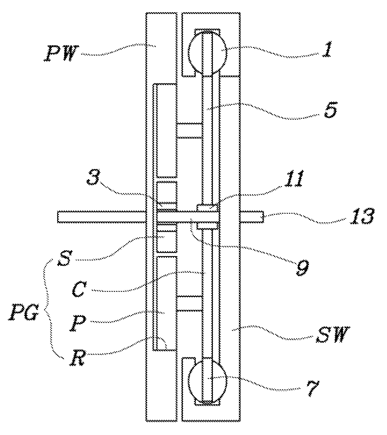
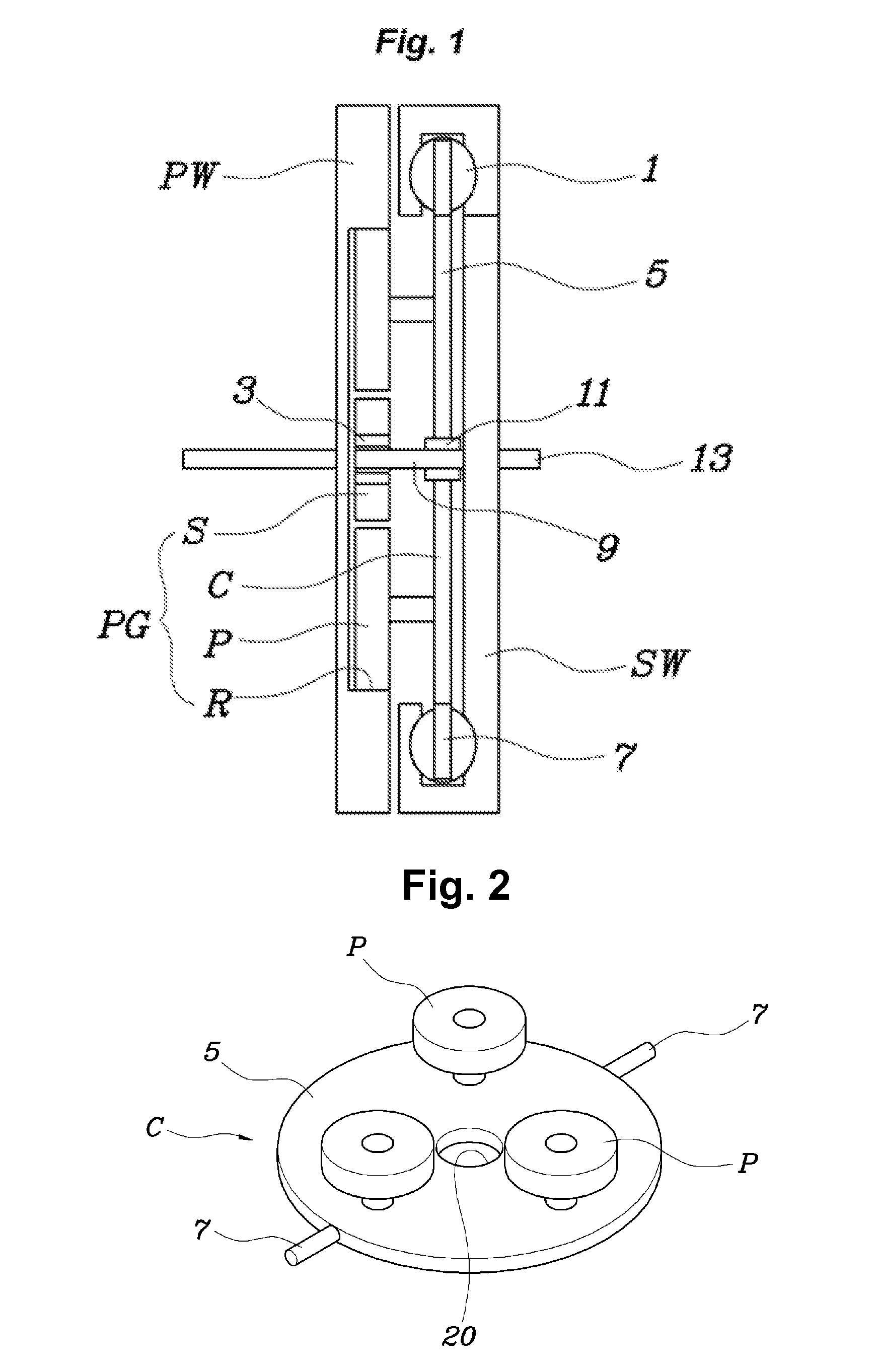
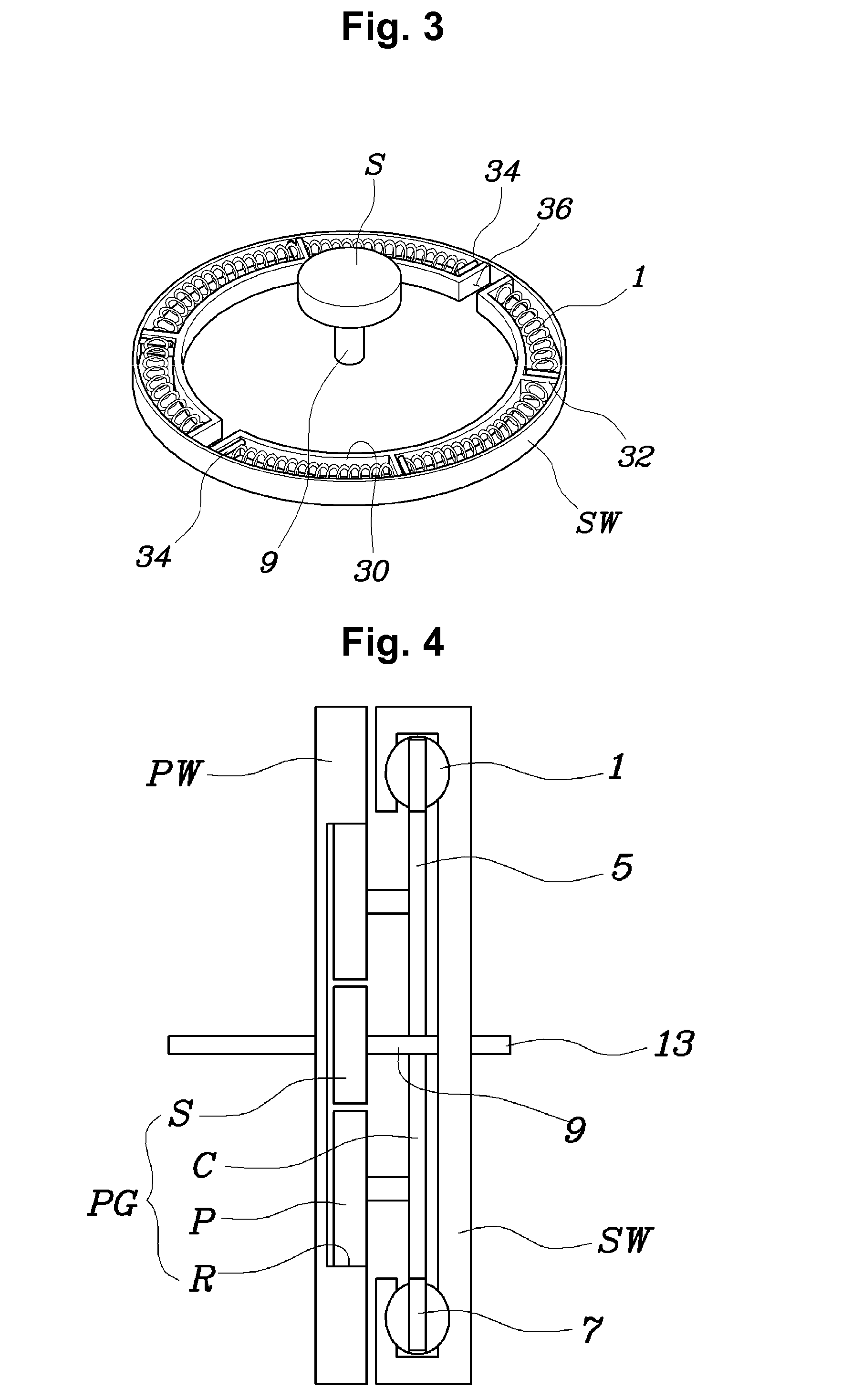
[0029]Referring to FIGS. 1 to 4, a flywheel according to an exemplary embodiment of the present invention includes, a rotary element that receives rotational force from an engine. a planetary gear set PG including other two rotary elements receiving a rotational force from the rotary element and elastically supported in relative r...


PUM


Abstract

A flywheel apparatus of an engine may include a primary wheel that receives a rotational force from the engine and has an integral ring gear, a secondary wheel that has a sun gear disposed coaxially with the ring gear, a carrier to which each rotary shaft of a plurality of planetary gears may be connected, the planetary gears being engaged between the integral ring gear and the sun gear, and a damping member elastically engaging between the carrier and the secondary wheel and providing an elastic force to the carrier during relative rotation between the carrier and the secondary wheel.

Description

CROSS-REFERENCE TO RELATED APPLICATION[0001]The present application claims priority to Korean Patent Application No. 10-2012-0030891 filed on Mar. 27, 2012, the entire contents of which is incorporated herein for all purposes by this reference.BACKGROUND OF THE INVENTION[0002]1. Field of the Invention[0003]The present disclosure relates to a flywheel of an engine. More particularly, it relates to the structure of a flywheel that reduces torsional vibration due to a change in torque generated in an engine.[0004]2. Description of Related Art[0005]An engine rotates a crankshaft, using power generated in the explosion stroke and the explosion stroke is not continuous so that torsional vibration is generated in the crankshaft by the continual power stroke and the rotational vibration is not preferable for continuously driving a vehicle. Therefore, the crankshaft is equipped with a flywheel that supplies relatively large rotational inertia to attenuate or reduce rotational vibration due t...

Claims


Application Information

Patent Timeline
Patent Type & Authority Patents(United States)
IPC IPC(8): F16H57/08
CPCF16H1/28F16F15/131Y10T74/2131F16F15/13157F16F15/31F16F15/30F02B77/00
Inventor HWANG, JAE WOONGJIN, YONG WOOKOH, WAN SOO
Owner HYUNDAI MOTOR CO LTD
Learn More