Oil filter device

a technology of oil filter and oil filter medium, which is applied in the direction of filtration separation, lubricant mounting/connection, separation process, etc., can solve the problems of high manufacturing technology requirements, relatively low filtration performance of filter medium, and higher maintenance effort, so as to achieve simple production, lower maintenance effort, and higher filtration performance

Active Publication Date: 2014-03-18
IBS FILTRAN KUNST METALLERZEUGNISSE
View PDF39 Cites 8 Cited by
  • Summary
  • Abstract
  • Description
  • Claims
  • Application Information

AI Technical Summary

Benefits of technology

[0005]It is an object of the invention to provide a suction oil filter device, an oil pan having such a suction oil filter device, and a filter system having a pressure oil filter device and such a suction oil filter device, the suction oil filter device being more simply producible and requiring a lower maintenance effort when working together with a pressure oil filter device, a higher filtration performance nonetheless being achieved.
[0010]At high viscosity and / or low temperatures of the oil, the ultrafine filter medium is hardly penetrated by the oil. With decreasing viscosity and / or increasing temperature of the oil, however, the ultrafine filter medium also has flow through it in the secondary area of the filter housing, so that the suction oil filter device achieves a higher filtration performance overall, a lower manufacturing outlay nonetheless being necessary. A special advantage of the suction oil filter device according to the invention is that oil which has already been better filtered passes through an additionally used pressure oil filter device, which typically has a relatively small overall size and a correspondingly small filter medium, so that if the suction oil filter device according to the present invention is used, the service life of the pressure oil filter device is increased. The maintenance effort for a filter system made of pressure oil filter device and suction oil filter device according to the invention is thus lower than previously.
[0011]According to one embodiment of the invention, the ultrafine filter medium and the fine filter medium are directly connected to one another. Even with a very turbulent flow, the relatively labile ultrafine filter medium may thus be situated securely, without a support or similar measures being necessary. The ultrafine filter medium and the fine filter medium are preferably connected to one another over their entire areas. This represents a very secure embodiment. However, it may already suffice if the ultrafine filter medium is only connected to the fine filter medium at multiple points, for example, at two ends and / or edges. An especially low manufacturing outlay is achieved in an embodiment in which the ultrafine filter medium is only directly connected to the fine filter medium at one end. This connection is preferably proximal to the oil inlet in an inside-outside filter device or proximal to the oil outlet in an outside-inside filter device. Oil penetrating into the filter housing thus presses the ultrafine filter medium against the fine filter medium, so that it is no longer necessary to fasten the ultrafine filter medium at the opposite free end. The reliable positioning of the ultrafine filter medium is basically assumed by the inflowing oil. The combination filter medium made of ultrafine filter medium and fine filter medium is thus very easily producible, in that a layer of the ultrafine filter medium is attached to the fine filter medium only in the area of the oil inlet in an inside-outside filter device or only in the area of the oil outlet in an outside-inside filter device. Further fastening of the two filter media in the interior of the filter pocket which is formed by the fine filter medium is no longer necessary.
[0013]According to a further embodiment, the suction oil filter device according to the invention may be implemented in such a manner that the ultrafine filter medium has an increasing distance to the fine filter medium beginning from the oil inlet, the maximum distance being a multiple of the thickness of the fine filter medium. This increasing distance allows the oil to flow around the ultrafine filter medium on the bottom side, so that more area of the fine filter medium may be penetrated. The spacing may preferably be achieved by a least one spacer. This ensures that a free end of the very mobile ultrafine filter medium is not pressed against the fine filter medium by the oil flow.
[0014]In the suction oil filter device according to the invention, it has been shown that a good filtration performance is achieved if the fine filter medium separates particles having a size which is greater than 50 μm and the ultrafine filter medium separates particles having a size which is greater than 20 μm.

Problems solved by technology

However, narrow tolerances are to be maintained, so that high requirements are placed on the manufacturing technology.
Because a minimum oil volume flow must additionally pass through the suction oil filter at high viscosity of the oil and / or at low temperature of the oil to achieve sufficient lubrication of an engine or a transmission, only a relatively low filtration performance may be achieved using the filter medium.
However, a relatively high dirt impingement is connected with the high filter performance, so that a filter medium of a pressure oil filter device must be replaced relatively frequently.
The higher filtration performance of the system made of suction oil filter device and pressure oil filter device may therefore often mean a higher maintenance effort in comparison to a suction oil filter device alone.

Method used


Image

  • Oil filter device
  • Oil filter device
  • Oil filter device

Examples


Embodiment Construction

[0026]The invention will now be described with reference to the drawing figures, in which like reference numerals refer to like parts throughout.

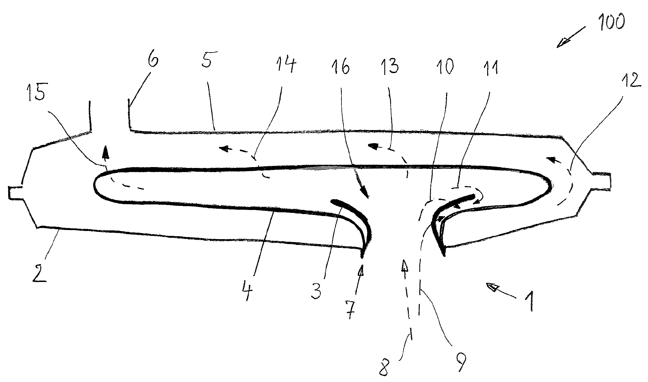
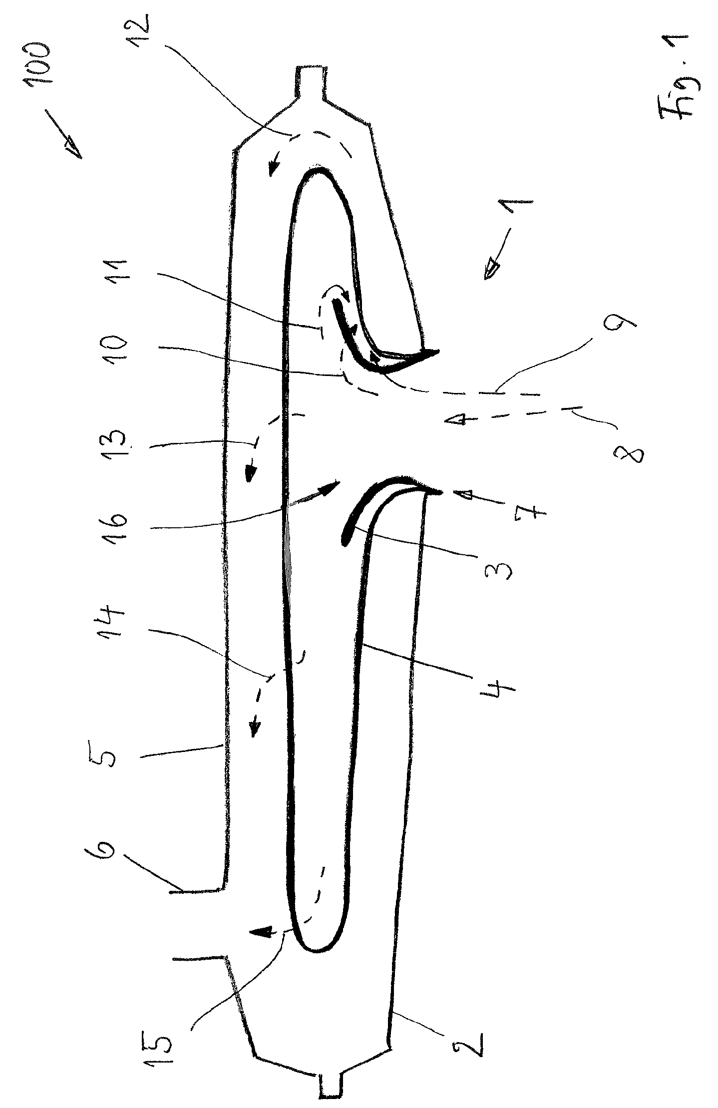
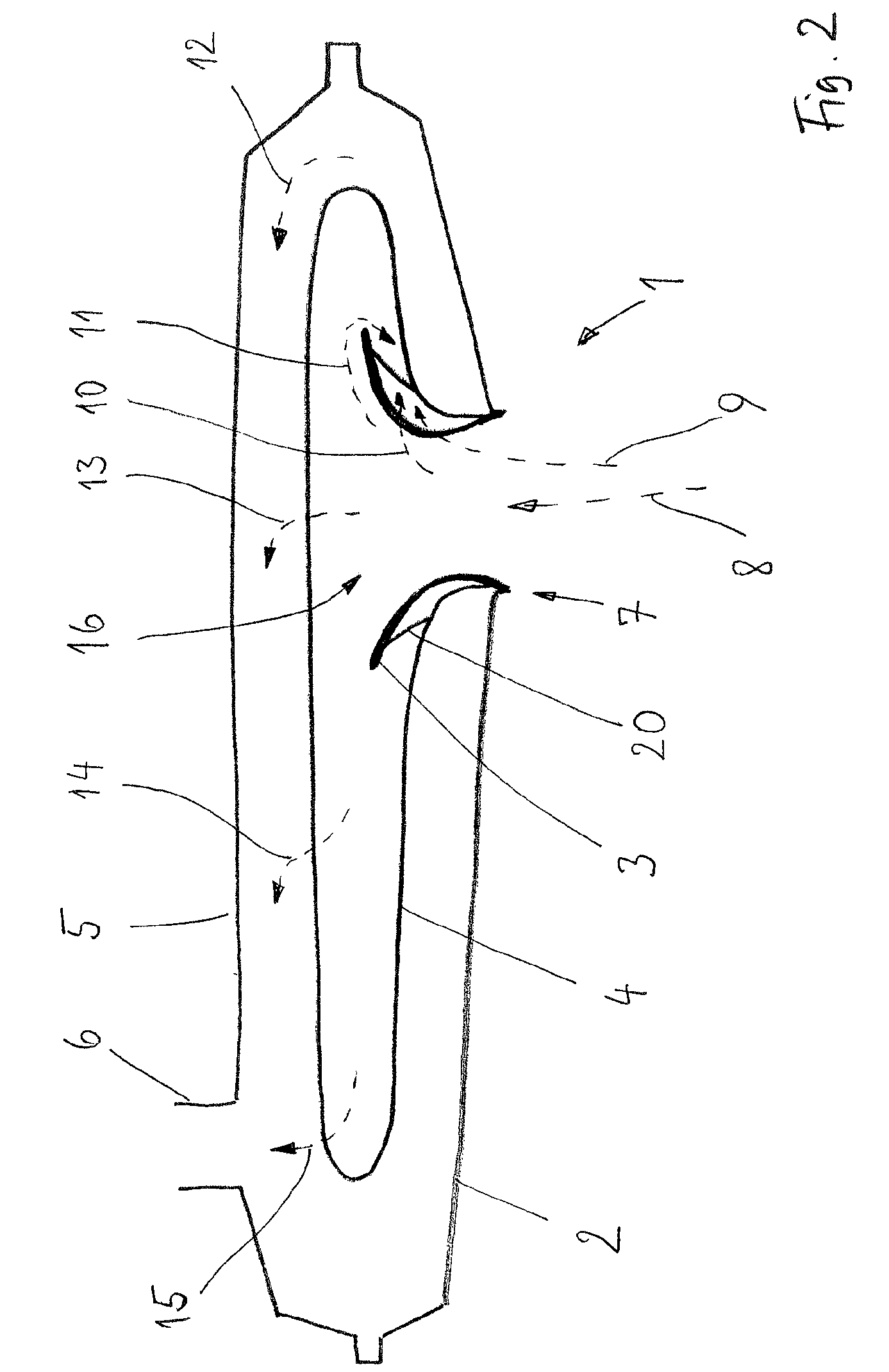
[0027]FIG. 1 shows a longitudinal cross-section of an embodiment of the oil filter device 100 according to the invention according to the inside-outside flow scheme. The device has an oil inlet 1 and an oil outlet 6, a suction pump being able to be attached to the latter. The oil inlet 1 is provided on one side in a filter lower shell 2, the oil outlet 6 being situated on an opposite side at the greatest possible distance from the oil outlet 1 in a filter upper shell 5. The filter lower shell 2 and the filter upper shell 5 together form a filter housing. Oil to be filtered passes through the oil inlet 1 into the filter device inner chamber 16 because of a partial vacuum generated by the suction oil pump.

[0028]The fine filter medium 4 is implemented as a filter pocket, the pocket opening being attached in the area of the oil inlet 1, see ref...


PUM

PropertyMeasurementUnit
sizeaaaaaaaaaa
sizeaaaaaaaaaa
temperatureaaaaaaaaaa

Abstract

The present invention provides a suction oil filter device for an engine or a transmission that has an oil inlet and an oil outlet on the filter housing, a suction oil pump connectable to the oil outlet, using which a partial vacuum may be generated between oil inlet and oil outlet, a fine filter medium and an ultrafine filter medium, which are situated between the oil inlet and the oil outlet. The fine filter medium is attached to the oil inlet or to the oil outlet, and the ultrafine filter medium is situated before the fine filter medium in the flow direction and in a secondary flow area of the filter housing. A high filtration performance may thus be achieved at low production outlay.

Description

CROSS REFERENCE TO RELATED APPLICATIONS[0001]This application claims priority to DE 102008014416.9, filed on Mar. 14, 2008, the disclosure of which is incorporated herein by reference in its entirety.BACKGROUND OF THE INVENTION[0002]The invention relates to a suction oil filter device for filtering oil in engines and transmissions, an oil pan having such an oil filter device, and a filter system having a pressure oil device and such a suction oil filter device.[0003]A suction oil filter device may be used for filtering oil in engines and transmissions. A pump is situated on the oil outlet of the filter device, the pump suctioning the oil to be filtered through a filter medium using partial vacuum. It is typical to situate a suction oil filter device directly in an oil sump of an oil pan, all of the oil to be filtered flowing through this suction oil filter device. Such a design requires only a small amount of additional installation space, is thus space-saving, and does not require ...

Claims


Application Information

Patent Timeline
Patent Type & Authority Patents(United States)
IPC IPC(8): B01D35/02B01D35/00B01D29/56B01D29/66B01D29/33
CPCB01D35/02B01D35/0273B01D2201/31B01D29/66F01M2001/1078B01D35/005B01D29/33B01D35/147B01D2201/188B01D29/56F01M11/03F01M1/10F01M1/02
Inventor STAUSBERG, WOLFGANGBEER, MARKUS
Owner IBS FILTRAN KUNST METALLERZEUGNISSE
Why Eureka
Try Eureka